The Critical Role of Pedal Geometry in Drivetrain Diagnostics
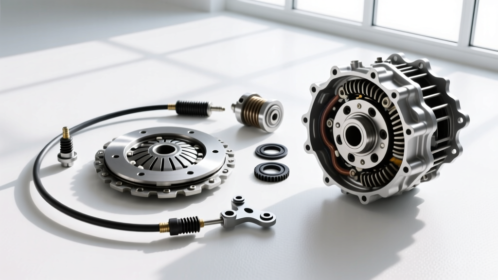
When diagnosing manual transmission issues—ranging from gear grind on the 2-3 shift to premature clutch disc glazing—technicians often bypass the simplest variable: pedal geometry. Before pulling a transmission or replacing a dual-mass flywheel (DMF), executing a rigorous clutch system inspection checklist is mandatory. The process of adjusting clutch pedal freeplay is not merely about driver comfort; it directly dictates the hydraulic stroke volume, release bearing preload, and clutch fork pivot kinematics. In 2026, with the proliferation of complex Concentric Slave Cylinders (CSC) and automated-manual hybrid architectures, understanding the baseline mechanical and hydraulic parameters is more critical than ever.
Phase 1: Measuring and Adjusting Clutch Pedal Freeplay
Freeplay is the distance the pedal travels before the master cylinder pushrod begins to displace fluid. Insufficient freeplay causes the release bearing to ride against the pressure plate fingers, leading to catastrophic bearing failure and clutch slip. Excessive freeplay results in incomplete disengagement, causing gear clash and synchro wear.
Step-by-Step Measurement Protocol
- Secure a digital caliper or a rigid steel ruler to the steering column shroud, aligning it with the center axis of the clutch pedal pad.
- Depress the pedal by hand until you feel the distinct resistance of the master cylinder piston engaging. Record this measurement as Freeplay.
- Continue depressing the pedal to the bump stop on the firewall. Record this as Total Stroke.
- Subtract Freeplay from Total Stroke to determine Effective Hydraulic Displacement.
Pro-Tip: Never rely on the "finger feel" method for precision diagnostics. A variance of just 0.15 inches in freeplay can alter the slave cylinder stroke by up to 0.06 inches at the clutch fork, which is enough to cause incomplete engagement on high-clamp-load aftermarket pressure plates.
Platform-Specific Specifications & Adjustment Methods
The method for adjusting clutch pedal mechanisms varies wildly by OEM platform. Below is a technical matrix detailing factory specifications, adjustment types, and critical torque values for common manual transmission applications.
| Platform / Transmission | Freeplay Spec | Adjustment Method | Master Cyl. Mount Torque | Slave Configuration |
|---|---|---|---|---|
| Honda Civic Si (K20 / 6-Speed) | 0.59 - 0.98 in. | Pushrod Clevis Pin | 18 lb-ft | External Cylinder |
| Ford Mustang GT (MT-82 / Getrag) | 0.50 - 1.00 in. | Pushrod / Firewall Shim | 22 lb-ft | Internal CSC |
| GM Camaro SS (T56 Magnum) | 0.75 - 1.25 in. | Pushrod Clevis Pin | 25 lb-ft | External Cylinder |
| Porsche 911 (997 / G50) | 0.20 - 0.40 in. | Master Cylinder Rod | 15 lb-ft | Internal CSC |
| Jeep Wrangler (NV3550 / AX15) | 1.00 - 1.25 in. | Pushrod Clevis Pin | 20 lb-ft | External Cylinder |
Phase 2: Hydraulic System Integrity and Fluid Analysis
Once pedal geometry is verified, the hydraulic circuit must be stress-tested. Most modern manual transmissions utilize DOT 3 or DOT 4 glycol-based brake fluid, which is highly hygroscopic. Moisture absorption lowers the fluid's boiling point and introduces compressibility into the system, manifesting as a spongy pedal or erratic engagement points during high-RPM shifts.
Fluid Testing and Bleeding Procedures
- Moisture Testing: Use a digital brake fluid tester. If moisture content exceeds 3 percent, a complete system flush is mandatory. Expect to pay $15 to $30 for a high-quality tester.
- Pressure Bleeding: Vacuum bleeders often draw air past the master cylinder pushrod seal, giving false readings. Always use a pressure bleeder (e.g., Motive Products 0107) set to 15-20 PSI. Higher pressures can rupture the delicate diaphragm inside the clutch master cylinder reservoir cap.
- Slave Cylinder Stroke Verification: For external slaves, measure the pushrod travel during a full pedal stroke. A healthy GM T56 external slave should exhibit 0.450 to 0.550 inches of total travel. Anything less indicates internal master cylinder bypass or a failing slave seal.
Phase 3: Mechanical Linkage and Release Bearing Diagnostics
If the hydraulics check out but the pedal still exhibits notchiness or lateral vibration, the fault lies within the bellhousing. This requires lifting the vehicle and, in many cases, dropping the transmission to inspect the clutch fork and pivot ball.
The Pivot Ball Wear Epidemic
In high-torque applications like the Ford MT-82 or GM T56, the stamped-steel clutch fork rides on a hardened steel pivot ball. Over 60,000 miles, the constant lateral load carves a microscopic trench into the pivot ball. According to Auto Service Professional, a pivot ball wear groove exceeding 0.020 inches will alter the clutch fork ratio, effectively stealing hydraulic stroke and causing incomplete disengagement. When performing a clutch replacement, always replace the pivot ball (e.g., GM part #12556184 or Ford upgrade kit) and apply a thin layer of molybdenum disulfide (moly) grease to the contact patch.
Concentric Slave Cylinder (CSC) Preload
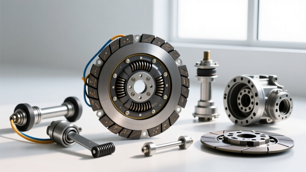
Vehicles equipped with internal CSCs (like the Porsche 997 or modern Nissan Z) eliminate the external fork entirely. The CSC rides directly on the transmission input shaft sleeve. When adjusting clutch pedal feel on a CSC-equipped vehicle, you are actually altering the internal fluid volume. If a new CSC is installed without properly bleeding the system at the master cylinder banjo bolt first, air will become trapped in the internal gallery, resulting in a pedal that drops to the floor and fails to return.
Phase 4: Flywheel Runout and Drivetrain Harmonics
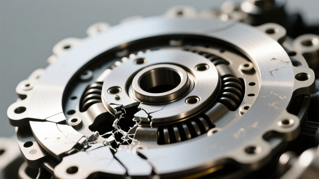
If your inspection checklist confirms perfect pedal freeplay, pristine hydraulic fluid, and zero mechanical slop, yet the vehicle still suffers from clutch chatter on engagement, the issue is likely flywheel runout or engine mount degradation.
Dial Indicator Runout Testing
Clutch chatter is the result of the friction disc grabbing and releasing unevenly. While often blamed on oil contamination, it is frequently caused by a warped flywheel or improper machining. To measure this:
- Mount a magnetic base dial indicator to the engine block, positioning the needle perpendicular to the flywheel friction surface.
- Rotate the crankshaft 360 degrees and record the Total Indicator Reading (TIR).
- Compare against OEM limits. Most factory Dual Mass Flywheels (DMF) allow up to 0.003 inches of lateral runout. Aftermarket single-mass aluminum flywheels (e.g., Fidanza, ACT) demand a much stricter tolerance of 0.001 inches.
Cost Reality Check: Replacing a failing Concentric Slave Cylinder requires transmission removal. While the CSC part itself may only cost $80 to $150, labor rates in 2026 average $130 to $180 per hour, pushing the total job cost to $900 to $1,500. Always replace the clutch disc, pressure plate, and flywheel simultaneously when a CSC fails.
Summary: The Diagnostic Hierarchy
Mastering the clutch system inspection checklist prevents misdiagnosis and unnecessary parts swapping. Always start at the pedal pad, verify the freeplay against the matrix above, pressure-bleed the hydraulics, and finally inspect the bellhousing kinematics. For further reading on manual transmission drivetrain harmonics and SAE clutch actuation standards, refer to technical papers published by SAE International and practical restoration guides from Hagerty Media.