The Evolution of Axle Rebuilds: Mechanical Meets Hydraulic
Rebuilding a modern limited-slip differential (LSD) requires far more than just swapping ring and pinion gears. As of 2026, the widespread integration of electronically controlled limited-slip differentials (e-LSDs) and advanced torque-vectoring axles in performance trucks and SUVs means technicians must master both mechanical tolerances and hydraulic principles. Whether you are servicing a traditional Ford 8.8-inch Traction-Lok or a modern ZF active rear axle, understanding the interplay between mechanical clutch preload and hydraulic actuation is critical for eliminating NVH (noise, vibration, and harshness) and ensuring optimal torque bias.
This step-by-step guide covers the complete rebuild procedure for a clutch-type LSD, with a specialized focus on hydraulic calibration and the engineering principles that govern modern axle performance.
What is the Differential Pressure Definition in Active Axles?
Before tearing into the carrier, it is vital to understand the differential pressure definition as it applies to active and clutch-type differentials. In hydraulic and electromechanical drivetrain systems, differential pressure ($\Delta P$) is defined as the precise delta between the main hydraulic line pressure (or baseline system pressure) and the specific clutch-apply pressure required to modulate torque transfer across the axle.
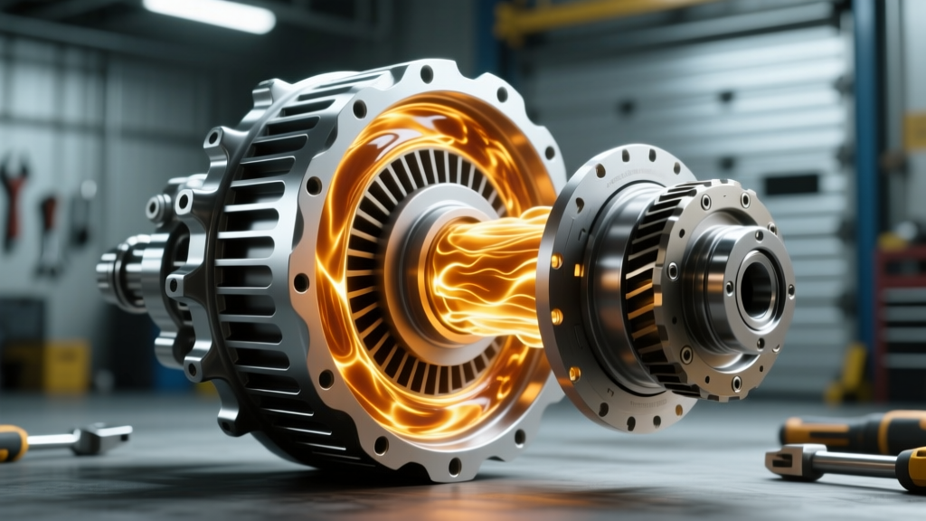
In an active e-LSD, a high-pressure pump generates baseline hydraulic fluid pressure. Solenoids then modulate the apply pressure to the clutch pack. The differential pressure definition dictates the exact threshold at which the clutch pack transitions from an open state to a locked state. If the mechanical rebuild does not account for the physical thickness of the clutch discs and the wave-spring preload, the hydraulic $\Delta P$ will be miscalibrated. This results in either premature clutch slip (causing shudder and overheating) or excessive lockup (causing tire chirping and binding during low-speed cornering). Proper mechanical shimming ensures the hydraulic differential pressure operates within the manufacturer's engineered window, typically between 15 and 45 PSI for apply modulation.
Pre-Rebuild Teardown and Failure Analysis
A successful rebuild begins with forensic teardown. Never skip the inspection phase, as it reveals the root cause of failure.
- Drain and Inspect Fluid: Look for metallic glitter (indicating bearing or gear wear) or a burnt smell (indicating clutch pack failure due to inadequate friction modifier or excessive slip).
- Measure Backlash Before Disassembly: Use a dial indicator with a magnetic base mounted to the axle housing. Measure ring gear backlash at three equidistant points. Factory spec is typically 0.006" to 0.010". If your pre-teardown reading was 0.020"+, the carrier bearings are likely collapsed.
- Extract the Carrier: Use a specialized carrier bearing puller (e.g., OTC 4530). Never pry between the ring gear and housing, as this will score the machined bearing seats.
- Inspect the Cross-Pin and Side Gears: In clutch-type LSDs, the cross-pin often wears a groove into the differential case. If the groove exceeds 0.005" in depth, the case must be replaced.
Step-by-Step Clutch Pack and Gear Assembly
For this procedure, we will reference the widely serviced Ford 8.8-inch clutch-type LSD (using an Eaton or Auburn replacement kit) and incorporate the necessary steps to ensure hydraulic and mechanical harmony.
Step 1: Case Preparation and Ring Gear Mounting
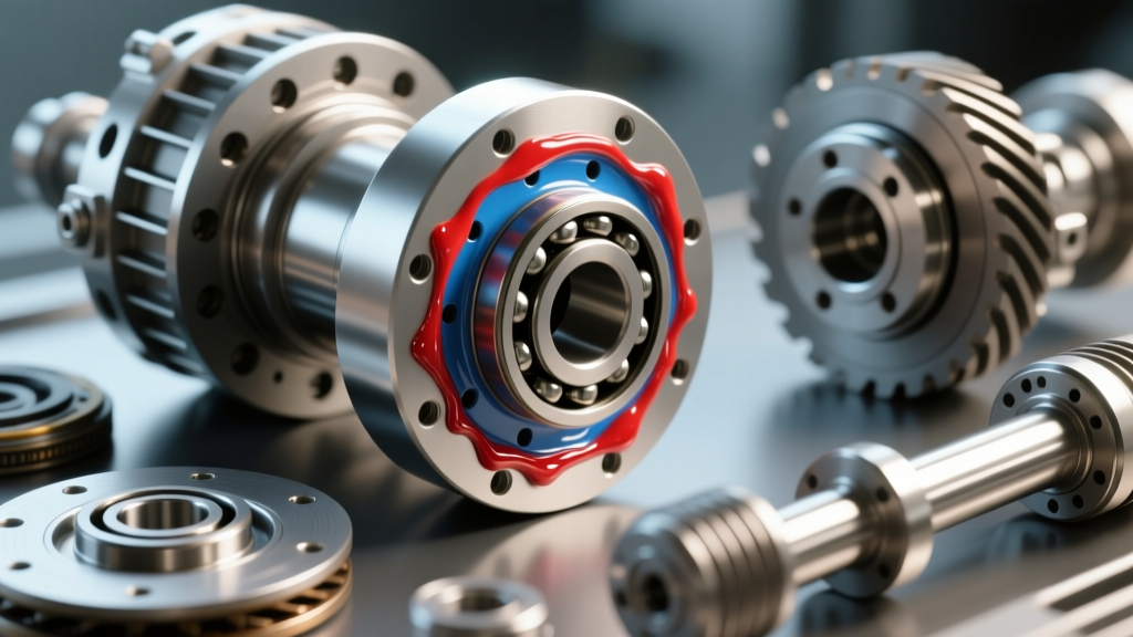
Clean the differential case with solvent and compressed air. Inspect the ring gear mounting surface for burrs. Apply a thin layer of Loctite 242 (blue) to the threads of the new ring gear bolts.
Torque Spec: Tighten the ring gear bolts in a crisscross pattern to 70-85 lb-ft. Do not reuse old ring gear bolts, as they are torque-to-yield or highly stressed fasteners.
Step 2: Clutch Pack Shimming and Preload
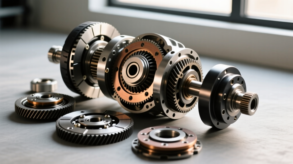
This is where the mechanical setup directly impacts the differential pressure definition in active or hydraulically assisted systems. The clutch pack consists of alternating friction discs (usually carbon-fiber or sintered bronze) and steel reaction plates.
- Soak all friction discs in the specified limited-slip friction modifier (e.g., Motorcraft XL-3 EST-M2C118-A) for a minimum of 15 minutes prior to assembly.
- Install the clutch packs onto the side gear hubs. Ensure the tabs on the steel plates align with the case slots, and the inner splines of the friction discs align with the side gear splines.
- Shim Selection: Use the S-spring or wave spring provided in the rebuild kit. If rebuilding an aftermarket unit like a Yukon Gear Dura Grip, use the provided shim kit to achieve the correct clutch pack clearance. The goal is to achieve a rotational breakaway torque of 40 to 60 lb-ft before the side gears begin to spin independently of the case.
Step 3: Side Gear and Cross-Pin Installation
Insert the side gears into the case, engaging them with the clutch packs. Slide the spider gears and cross-pin into place. Secure the cross-pin with the factory roll pin or lock bolt.
Torque Spec: If using a lock bolt, apply Loctite 242 and torque to 15-25 lb-ft, depending on the specific axle manufacturer specification.
Step 4: Carrier Bearing Installation and Backlash Setup
Press new carrier bearings (e.g., Timken SET-10 for Ford 8.8) onto the differential case using a hydraulic press and the appropriate bearing race driver. Never press on the outer cage; always press on the inner race.
Install the carrier into the housing with the adjustment shims or threaded adjusters. Set the backlash to 0.008" using a dial indicator. Rotate the carrier 360 degrees to ensure the backlash remains consistent across all gear teeth.
Step 5: Pattern Verification
Apply yellow gear marking compound to the ring gear. Rotate the pinion to check the contact pattern. The drive pattern should be centered on the tooth face, slightly biased toward the heel. The coast pattern should be centered or slightly toward the toe. Adjust pinion depth shims as necessary to achieve the ideal pattern.
Hydraulic Calibration and Fluid Specifications
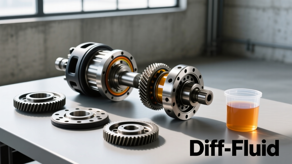
Once the mechanical rebuild is complete, the axle must be filled with the correct fluid to ensure the differential pressure definition is maintained during operation. Using standard gear oil without friction modifiers in a clutch-type LSD will cause the clutches to grab aggressively, leading to severe chatter and catastrophic failure of the friction material.
For modern active differentials that rely on hydraulic pumps to modulate clutch pressure, the fluid's viscosity index and anti-foaming agents are paramount. Air entrainment in the hydraulic fluid will cause a spongy $\Delta P$ response, leading to delayed torque vectoring and erratic traction control interventions.
Torque Specs and Clearance Data Table
Reference the following specifications for common clutch-type and active LSD platforms. Always verify with the specific OEM service manual for your exact model year.
| Specification | Ford 8.8" (Traction-Lok) | GM 9.5" (Eaton Posi) | ZF ELSD (Active e-LSD) |
|---|---|---|---|
| Ring Gear Bolt Torque | 70 - 85 lb-ft | 90 - 110 lb-ft | 85 - 95 lb-ft |
| Pinion Nut Torque (Crush Sleeve) | 160 - 220 lb-ft | 180 - 240 lb-ft | N/A (Solid Spacer) |
| Target Backlash | 0.006" - 0.010" | 0.005" - 0.009" | 0.004" - 0.008" |
| Clutch Breakaway Torque | 40 - 60 lb-ft | 50 - 80 lb-ft | Hydraulically Modulated |
| Fluid Capacity (Approx.) | 2.5 - 3.0 Pints | 3.5 - 4.0 Pints | 2.0 - 2.5 Liters |
| Required Friction Modifier | XL-3 (4 oz) | ACDelco 10-4016 (4 oz) | OEM Specific e-LSD Fluid |
Final Break-In and Testing Protocol
After assembling the axle and filling it with the specified synthetic 75W-90 or 75W-140 gear oil and friction modifier, a proper break-in procedure is mandatory. Drive the vehicle in a safe, open area and perform 10 to 15 slow, tight figure-eight maneuvers. This forces the clutch packs to slip slightly under load, burnishing the friction material and distributing the friction modifier evenly across the clutch surfaces.
Following the figure-eights, complete a 30-mile highway drive cycle to bring the gear oil up to operating temperature, allowing the ring and pinion to seat properly. Re-check the differential fluid level after the axle cools, as the fluid level will drop slightly as the oil fills the internal galleries and clutch pack reservoirs.
Expert Resources and Further Reading
For advanced installation diagrams and carrier-specific shim calculators, consult the Yukon Gear & Axle Installation Guides. Additionally, for in-depth engineering specifications on clutch-type and locking differentials, review the Eaton Automotive Differentials Catalog. Understanding both the mechanical tolerances and the differential pressure definition of modern hydraulic systems will ensure your axle rebuilds perform flawlessly on the street and the track.