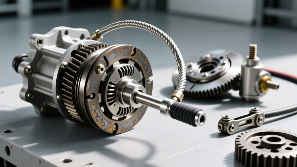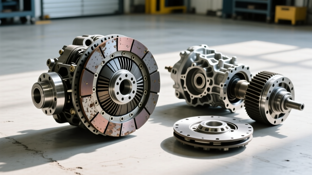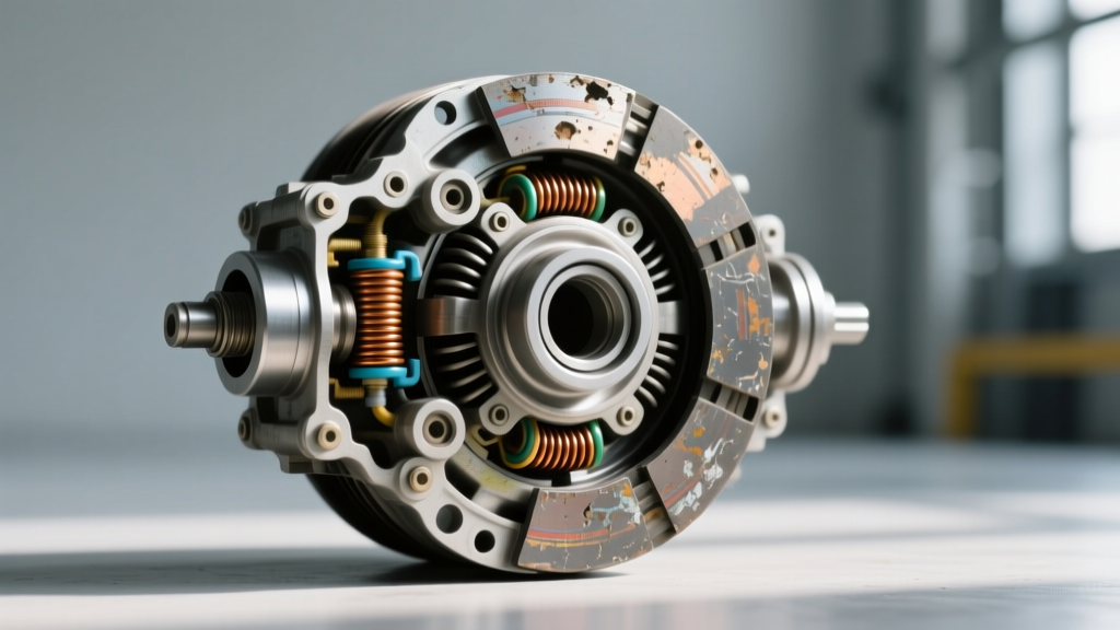
Understanding the Electromagnetic Clutch and Relay Architecture
While automotive enthusiasts frequently associate the term "clutch" with manual drivetrain friction assemblies, the HVAC system relies on a highly specialized electromagnetic clutch to engage the A/C compressor. As of 2026, although many modern passenger vehicles utilize variable-displacement compressors with internal PWM control valves, millions of legacy vehicles, heavy-duty trucks, and off-highway equipment still depend on the traditional electromagnetic clutch and AC clutch relay architecture. Diagnosing compressor engagement issues requires a fundamental understanding of how the relay acts as the primary diagnostic gateway for identifying electromagnetic clutch wear signs and lifespan indicators.
The AC clutch relay is a simple electromechanical switch controlled by the Powertrain Control Module (PCM) or HVAC control head. When the PCM grounds the relay coil circuit, it closes the high-amperage switch contacts, sending 12V battery power directly to the compressor clutch coil. However, when the clutch fails to engage, technicians often prematurely condemn the relay or the compressor. A true technical deep-dive requires using the relay circuit to isolate electrical faults from mechanical clutch wear, specifically focusing on air gap degradation, thermal coil breakdown, and friction plate deterioration.
The Role of the AC Clutch Relay in System Diagnostics
Before measuring clutch wear, the AC clutch relay must be verified as the baseline control node. The relay bridges the low-current PCM trigger circuit with the high-current compressor feed. By monitoring the relay's physical and electrical behavior, a technician can immediately bifurcate the diagnostic tree:
- Relay Clicks, Clutch Fails to Engage: The PCM trigger and relay coil are functional. The fault lies downstream in the high-amperage circuit, the clutch coil, or the mechanical air gap.
- Relay Fails to Click: The fault lies upstream (PCM trigger, low-pressure switch, ambient temperature sensor) or within the relay coil itself.
- Relay Chatters Rapidly: This often indicates a severe voltage drop, a failing PCM driver transistor, or an intermittent short in the clutch coil wiring harness.
According to diagnostic guidelines published by the Mobile Air Climate Systems Association (MACS), verifying relay output voltage under load is critical. A relay may click, but if the internal switch contacts are pitted from years of high-amperage arcing, it may only pass 8 volts to the clutch coil instead of the required 12.5+ volts, mimicking a worn clutch coil.
Electromagnetic Clutch Wear Signs & Lifespan Indicators
Unlike a manual transmission clutch that wears via friction material loss, an A/C electromagnetic clutch "wears" through magnetic circuit degradation, thermal fatigue, and mechanical bearing failure. Here are the primary lifespan indicators.
1. Air Gap Degradation (The Silent Killer)
The most common and misdiagnosed wear sign in an electromagnetic clutch is the widening of the air gap between the rotor (pulley) and the armature (friction plate). Over tens of thousands of engagement cycles, the friction surfaces wear down, and the armature shim stack settles. This increases the physical distance the magnetic field must bridge.
Magnetic flux density drops exponentially with distance. A typical Denso or Harrison compressor specifies an air gap between 0.3mm and 0.6mm (0.012" - 0.024"). If the gap widens to 0.8mm or beyond, the clutch may engage when the engine bay is cold. However, as under-hood temperatures rise, the copper windings inside the clutch coil heat up. According to Ohm's Law, as temperature increases, electrical resistance increases. This resistance drop reduces amperage, weakening the magnetic field. The weakened field can no longer pull the armature across the widened air gap, resulting in the classic "works cold, blows warm when hot" symptom. This is frequently misdiagnosed as a faulty AC clutch relay when it is actually a mechanical wear indicator.
2. Clutch Coil Thermal Breakdown
The electromagnetic coil is essentially a tightly wound spool of copper wire encapsulated in epoxy. Over a lifespan of 10 to 15 years, thermal cycling causes micro-fractures in the wire or the epoxy casing, allowing moisture ingress and shorting between windings. A healthy clutch coil typically measures between 3.0 and 5.0 ohms at 20°C (68°F). If your multimeter reads below 2.5 ohms, the coil has internal shorts and will draw excessive amperage, potentially melting the AC clutch relay contacts or damaging the PCM driver. If it reads infinite (OL), the internal thermal fuse has blown or the wire has severed.
3. Pulley Bearing and Friction Plate Wear
The clutch pulley rides on a sealed angular contact bearing. When this bearing reaches the end of its lifespan, it introduces rotational drag. If the drag exceeds the holding torque of the electromagnetic coil, the clutch will slip, generating immense heat that will quickly burn out the coil and destroy the relay contacts. Audible signs include a continuous metallic growl when the A/C is turned off (pulley spinning freely) or a high-pitched squeal when engaged.
Step-by-Step AC Clutch Relay & Component Testing Matrix
To accurately separate relay faults from clutch wear, follow this structured testing protocol using a digital multimeter (DMM) and a set of metric feeler gauges.
| Test Point / Component | Multimeter Setting | Expected Specification | Wear / Failure Indicator |
|---|---|---|---|
| Relay Coil (Pins 85 & 86) | Ohms (Ω) | 60 - 120 Ω | OL (Open) or < 40 Ω (Shorted) |
| Relay Switch (Pins 30 & 87) | Volts DC (Under Load) | Battery Voltage (12.5V+) | < 11.0V (Pitted internal contacts) |
| Clutch Coil (At Compressor Pigtail) | Ohms (Ω) | 3.0 - 5.0 Ω (at 20°C) | < 2.5 Ω (Shorted) or OL (Blown) |
| Clutch Air Gap (Rotor to Armature) | Feeler Gauge (mm) | 0.30mm - 0.60mm | > 0.75mm (Requires shim removal) |
| Clutch Holding Torque | Torque Wrench (ft-lbs) | 15 - 25 ft-lbs (Varies by model) | Slipping below 12 ft-lbs |
Lifespan Indicators: When to Re-shim vs. Replace
Identifying the exact wear sign dictates the repair strategy. Replacing the AC clutch relay will not fix a widened air gap, and replacing the entire compressor is a waste of money if only the clutch coil has failed. Resources from ACKits emphasize that rebuilding the clutch assembly is highly cost-effective if the compressor shaft seal and internal valves are still healthy.
| Component | Average Lifespan | Repair Action | Estimated Cost (Parts) |
|---|---|---|---|
| AC Clutch Relay | 100,000+ Cycles | Replace (e.g., SMP R3146) | $10 - $25 |
| Armature / Friction Plate | 120,000 Miles | Remove shims to reset air gap | $0 (Labor only) or $35 for new plate |
| Electromagnetic Coil | 10 - 15 Years | Replace coil & bearing | $45 - $90 |
| Pulley Bearing | 80,000 Miles | Press out and replace bearing | $15 - $30 |
| Complete Compressor Assy | 150,000+ Miles | Replace entire unit & flush system | $250 - $700+ |
Advanced Edge Cases: PCM Drivers and Diode Protection
When diagnosing the AC clutch relay circuit, technicians must be aware of the protective diode often integrated into modern relay housings or the compressor clutch connector. When the magnetic field of the clutch coil collapses upon deactivation, it generates a massive reverse-voltage spike (inductive kickback). If the suppression diode fails, this spike can backfeed into the PCM, eventually frying the solid-state transistor that controls the relay ground.
If you find a melted AC clutch relay connector or a PCM that no longer triggers the relay ground, do not simply replace the relay. You must test the clutch coil for inductive spikes using an oscilloscope. A healthy coil should show a clean voltage decay curve. A coil with degrading internal insulation will exhibit erratic, high-amplitude voltage ringing that destroys relays and PCM drivers. For deeper electrical schematics and OEM relay testing procedures, the Standard Motor Products (SMP) Tech Library provides excellent reference materials on automotive relay diagnostics and inductive load management.
Summary
Diagnosing A/C compressor engagement issues requires looking past the simple "click" of the AC clutch relay. By systematically measuring relay voltage drop under load, verifying clutch coil resistance at operating temperatures, and physically measuring the armature air gap with feeler gauges, technicians can accurately pinpoint electromagnetic clutch wear signs. Understanding these lifespan indicators prevents unnecessary compressor replacements, ensures long-term HVAC reliability, and restores optimal cabin cooling performance.