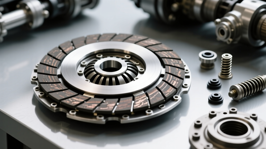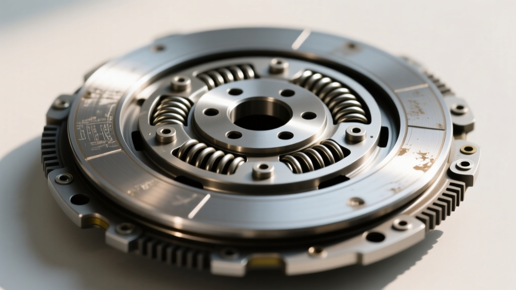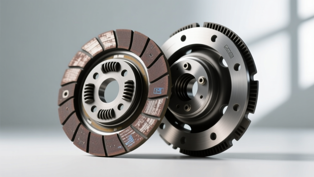
The Intersection of HVAC and Fr clutch Technology
While the Clutch Disc, Plate & Components category at AutoGearNexus primarily focuses on high-torque transmission drivetrains, the fundamental physics of friction engagement apply equally to automotive HVAC systems. When diagnosing or replacing an ac compressor clutch kit, you are essentially dealing with a miniature, electromagnetically actuated friction clutch. The compressor hub acts as the driven friction disc, while the machined face of the pulley rotor serves as the mating pressure plate and flywheel surface.
In 2026, with the proliferation of advanced variable-displacement compressors and strict refrigerant containment regulations, a slipping or dragging AC clutch is no longer just a comfort issue—it can trigger cascading serpentine belt failures or ECU limp-mode codes. This step-by-step guide details the precise inspection protocols for the friction disc and mating plate of an AC compressor clutch assembly.
Essential Tools for Precision Inspection
Before dismantling the assembly, gather the following precision instruments. Guesswork with AC clutches leads to rapid friction material degradation.
- Metric/Imperial Feeler Gauges: For air gap measurement (0.010" to 0.040" range).
- Dial Indicator with Magnetic Base: To measure pulley and friction disc runout.
- Digital Multimeter (DMM): For electromagnetic coil resistance validation.
- Inch-Pound Torque Wrench: Critical for the center hub retaining bolt.
- Isopropyl Alcohol & Lint-Free Wipes: For cleaning friction surfaces without leaving residue.
Step 1: Visual and Metallurgical Inspection of Friction Surfaces
The friction disc (hub plate) in a modern ac compressor clutch kit is typically manufactured from sintered iron or specialized high-carbon steel, designed to withstand high-slip heat generation during engagement. The mating surface on the pulley rotor is machined cast iron or steel.
Identifying Thermal and Chemical Damage
Clean both the hub disc and the pulley rotor face with isopropyl alcohol. Inspect for the following specific failure modes:
- Glazing and Heat Checking: Look for microscopic, spider-web-like thermal cracks on the pulley face. If the friction disc shows a mirror-like glaze, the coefficient of friction has dropped below the threshold required to lock the compressor shaft, resulting in continuous micro-slipping.
- Oil Contamination (The Silent Killer): Refrigerant compressor oils (PAG 46, PAG 100, or POE for EV systems) will destroy the friction coefficient of the clutch disc. If you see a dark, wet ring around the center hub, the compressor front shaft seal has failed. Do not install a new clutch kit without replacing the compressor or shaft seal.
- Scoring and Galling: Deep radial grooves indicate that the clutch was allowed to slip under high head-pressure conditions for an extended period, literally machining away the friction material.
Step 2: Air Gap Measurement and Adjustment
The air gap between the friction disc and the pulley plate is the single most critical specification in an ac compressor clutch kit. If the gap is too wide, the electromagnetic coil cannot generate enough flux density to pull the disc against the spring tension, causing slip and burn. If too narrow, the disc will drag against the pulley when disengaged, creating parasitic drag and premature bearing wear.
Reference Specifications by Compressor Model
According to technical service documentation from Sanden International and Denso Global, tolerances are incredibly tight. Reference the table below for common OEM compressor platforms:
| Compressor Platform | Target Air Gap (in / mm) | Max Allowable Wear Limit | Coil Resistance (12V Sys) |
|---|---|---|---|
| Denso 10S17C / 10S20C | 0.018" - 0.028" (0.45 - 0.71mm) | 0.035" (0.89mm) | 3.2 - 4.5 Ω |
| Sanden SD7V16 / SD7H15 | 0.015" - 0.025" (0.38 - 0.63mm) | 0.032" (0.81mm) | 3.6 - 4.8 Ω |
| GM R4 / V5 / CVC | 0.020" - 0.030" (0.50 - 0.76mm) | 0.040" (1.01mm) | 3.0 - 4.2 Ω |
| Harrison HT6 / DA6 | 0.018" - 0.028" (0.45 - 0.71mm) | 0.035" (0.89mm) | 3.4 - 4.6 Ω |
Measurement Technique: Insert a feeler gauge at three equidistant points around the circumference of the clutch. The friction disc must be perfectly parallel to the pulley plate. A variance of more than 0.005" between measurement points indicates a bent hub plate or a failing pulley bearing.
Adjusting the Air Gap
If the gap is out of specification on a newly installed ac compressor clutch kit, adjustment is achieved by adding or removing precision machined shims located on the compressor shaft beneath the hub. Never attempt to bend the friction disc ears to adjust the gap; this alters the spring tension and will lead to catastrophic harmonic vibration at high RPM.
Step 3: Hub Spline and Center Plate Integrity Check
The driven friction disc connects to the compressor shaft via an involute spline or a Woodruff key. Inspect the internal splines of the hub plate for 'step wear' or 'rust jacking.' Rust jacking occurs when moisture infiltrates the spline interface, creating iron oxide that expands and micro-fractures the hub plate. If the hub plate shows any hairline cracks radiating from the spline root, the entire kit must be rejected.
Apply a microscopic amount of anti-seize or specific spline grease (as dictated by the OEM service manual) to the compressor shaft before sliding the new friction disc into place. Over-application will result in grease migrating to the friction surfaces via centrifugal force.
Step 4: Runout and Bearing Validation
Mount a dial indicator to a stable point on the engine block or compressor casing. Rest the probe on the outer edge of the pulley rotor (the mating pressure plate surface). Rotate the pulley by hand. Total Indicator Reading (TIR) should not exceed 0.020" (0.50mm). Excessive runout indicates a failing pulley bearing or a warped rotor casting. A warped rotor will cause the air gap to fluctuate dynamically while the engine is running, leading to intermittent engagement and severe localized hot-spotting on the friction disc.
Torque Specifications and Reassembly Protocol
The center retaining bolt that secures the friction disc hub to the compressor shaft is a high-stress fastener. It must withstand the sudden torsional shock of the compressor pistons engaging against high-side refrigerant pressures.
- Standard M8x1.25 Center Bolt: Torque to 15 - 18 Nm (11 - 13 lb-ft). Do not exceed this, or you risk stripping the threads inside the compressor shaft or snapping the bolt head.
- Threadlocker: Apply a single drop of medium-strength threadlocker (e.g., Loctite 243) to the bolt threads. The compressor shaft is often blind-tapped, meaning fluid can hydro-lock the bolt if over-applied.
2026 Market Context: Sourcing and Pricing
When sourcing an ac compressor clutch kit (which includes the friction hub/disc, pulley rotor, bearing, and electromagnetic coil), expect to pay between $65 and $145 for premium OEM-equivalent brands like Four Seasons, GPD, or Denso First Time Fit. Avoid unbranded aftermarket kits under $40; these frequently utilize substandard sintered iron for the friction disc that lacks the necessary porosity for heat dissipation, leading to failure within the first 5,000 miles.
Note on EV Applications: As of 2026, the majority of Electric and Hybrid vehicles utilize high-voltage (200V-400V) inverter-driven scroll compressors (e.g., Denso ES18 or Sanden SCS). These units do not use a traditional electromagnetic ac compressor clutch kit. Instead, they are direct-drive or utilize internal electronic clutches. If you are working on an EV HVAC system, do not attempt to apply the mechanical friction disc inspection steps outlined above; refer instead to the manufacturer's high-voltage inverter diagnostic flowcharts.
Final Verification
Once the ac compressor clutch kit is installed and torqued to spec, apply 12V directly to the coil terminals via a fused jumper wire. Listen for a sharp, definitive 'clack' indicating full friction surface mating. Measure the coil amperage draw; a healthy 12V AC clutch coil should draw between 2.5 and 4.0 amps. An amperage spike indicates a shorted coil, while a low draw suggests high internal resistance or a failing connector pigtail. Proper inspection of the disc and plate ensures the mechanical side of the clutch is flawless, allowing the electromagnetic system to perform exactly as engineered.