The GM 6L80E Thermal Management Crisis
The GM 6L80E (RPO MYC/MYD) is a robust six-speed automatic transmission found in millions of Silverados, Sierras, and Tahoes. However, its internal architecture—specifically the Transmission Electro-Hydraulic Control Module (TEHCM)—is highly sensitive to heat. When towing or hauling, the torque converter generates massive amounts of thermal energy. If the transmission fluid exceeds 220°F, the synthetic Dexron VI fluid begins to shear and oxidize, leading to torque converter shudder, solenoid failure, and eventual clutch pack burnout.
Worse, GM equipped many 6L80E applications with a factory thermal bypass valve in the cooler lines. This valve restricts fluid flow to the radiator cooler until the fluid reaches roughly 180°F, intended to help the transmission 'warm up' in freezing climates. In reality, it creates a dangerous thermal lag during heavy-load summer driving. Upgrading your cooling system and monitoring it accurately is not optional for modified or towing rigs; it is mandatory.
Transmission Cooler Types: Selecting the Right Core
When selecting an auxiliary transmission cooler for the 6L80E, you must balance heat rejection with fluid pressure drop. The 6L80E relies on precise line pressure for clutch application; a cooler that restricts flow will trigger P0877 (Transmission Fluid Pressure Sensor/Switch D Circuit Low) or cause delayed shifts.
Tube-and-Fin vs. Plate-and-Fin vs. Stacked-Plate
Understanding the physical design of the cooler core dictates its efficiency. Here is how the three primary designs stack up for heavy-duty applications:
| Cooler Type | Design Profile | Pressure Drop | Heat Rejection | Best Application |
|---|---|---|---|---|
| Tube-and-Fin | Serpentine tubes pressed through stamped fins. | High (Restrictive) | Low | Light-duty daily drivers, older vehicles. |
| Plate-and-Fin | Horizontal aluminum plates with corrugated fins. | Moderate | Medium | Class II towing, moderate upgrades. |
| Stacked-Plate (LPD) | Brazed aluminum plates forming turbulator channels. | Low (LPD design) | High | Heavy towing, 6L80E/6L90E upgrades. |
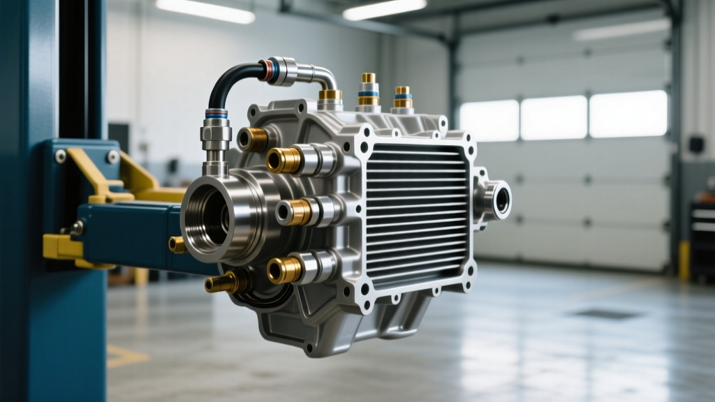
For the 6L80E, a Stacked-Plate cooler with a Low Pressure Drop (LPD) design is the only acceptable choice. The Tru-Cool LPD4544 (rated for 24,000 GVW) is the industry benchmark. It provides maximum surface area for heat exchange while maintaining the critical line pressure required by the TEHCM.
The Telemetry Gap: Why Factory Sensors Fall Short
The factory 6L80E temperature sensor is located internally, reading the sump temperature inside the transmission pan. While useful for the TCM to calculate shift firmness and lockup schedules, sump temperature is a lagging indicator. It does not tell you how effectively your auxiliary cooler is rejecting heat in real-time.
To truly evaluate your cooling system's Delta-T (temperature differential), you must install an inline transmission temperature sensor on the cooler return line. By measuring the fluid after it has passed through the radiator and auxiliary cooler, but before it re-enters the transmission, you gain actionable data on the cooler's actual thermal efficiency.
Step-by-Step 6L80E Cooler & Sensor Installation Guide
This model-specific repair guide covers bypassing the factory thermal restrictor, mounting a stacked-plate cooler, and splicing in an inline transmission temperature sensor for precise telemetry.
Phase 1: Thermal Bypass Valve Delete
Before routing new lines, eliminate the factory thermal bypass valve. On many 2007-2014 GMT900 trucks, this valve is integrated into the upper transmission cooler line adapter fitting.
- Removal: Use a 22mm line wrench to remove the factory adapter from the transmission case.
- Replacement: Install a billet aluminum bypass delete tube (e.g., Fleece Performance or PPE). This ensures 100% of the fluid flows to the coolers at all times.
- Torque Spec: Torque the new adapter to 25 ft-lbs using a new OEM O-ring.
Phase 2: Mounting the Stacked-Plate Cooler
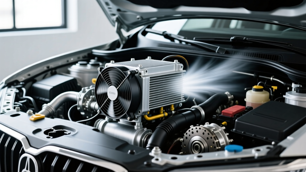
Mount the Tru-Cool LPD4544 in front of the A/C condenser. Use zip-ties with the provided rubber isolator pads to prevent core vibration damage. Ensure the inlet and outlet ports are oriented to prevent air pockets; ideally, fluid should enter the bottom port and exit the top port, though LPD cross-flow designs are somewhat forgiving.
Phase 3: Integrating the Inline Transmission Temperature Sensor
This is the most critical step for data accuracy. You will install the sensor on the return line (the line coming back from the radiator/cooler assembly to the lower transmission fitting).
- Cut the Return Line: Locate the 5/8-inch rubber transmission return hose. Cut a 3-inch section out using a clean tubing cutter or sharp hose shears.
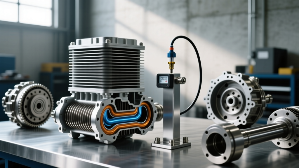
- Prepare the Sensor Housing: You will need a billet aluminum inline sensor housing with 5/8-inch hose barbs on each end and a 1/8-inch NPT port in the center (available from manufacturers like Earl's Performance or AutoMeter).
- Install the Sensor: Wrap the threads of your AutoMeter 1/8-inch NPT transmission temperature sensor with high-temperature Teflon paste (do not use standard Teflon tape, which can shred and clog TEHCM solenoids). Thread the sensor into the housing and torque to 18 ft-lbs.
- Splice the Housing: Slide two stainless steel T-bolt clamps onto the cut transmission hose. Insert the billet housing barbs into the hose and tighten the clamps to 45 in-lbs.
Expert Warning: Never install the inline transmission temperature sensor on the pressure/flow line exiting the transmission. The fluid velocity and pulsation from the transmission pump can cause erratic gauge readings and, in extreme cases, fatigue the sensor probe. Always install on the low-pressure return side.
Phase 4: Hose Routing and Securing
Use high-pressure, oil-resistant SAE J1532 transmission cooler hose. Avoid routing hoses near the exhaust manifolds or the DPF (Diesel Particulate Filter) on Duramax-equipped variants. Secure lines every 12 inches using Adel clamps (cushioned P-clamps) to prevent chafing against the frame or suspension components.
Bleeding the System and Verifying Telemetry
The GM 6L80E holds approximately 11.2 quarts of fluid when completely dry, but a cooler and line upgrade will typically require an additional 1 to 1.5 quarts of ACDelco Dexron VI to compensate for the increased volume of the stacked-plate core and the auxiliary lines.
- Fill the transmission dipstick tube with 2 quarts of Dexron VI to prime the system.
- Start the engine and let it idle. Cycle the gear selector through P-R-N-D, pausing for 3 seconds in each gear to fill the clutch apply circuits.
- With the engine still idling and the vehicle on level ground, check the fluid level. Add fluid incrementally until it reaches the lower 'Cold' mark on the dipstick.
- Take the vehicle for a 15-mile test drive. Monitor your new inline transmission temperature sensor.
Interpreting Your New Data
Once fully warmed up, the inline sensor should read 20°F to 40°F cooler than the factory sump temperature displayed on your OBD2 scanner. If your inline sensor reads 180°F (post-cooler) and the factory TCM reads 210°F (sump), your cooler is functioning perfectly, shedding 30 degrees of heat before the fluid re-enters the transmission. If the Delta-T is less than 10 degrees, you have a flow restriction, an air-bound cooler, or insufficient airflow through the stacked-plate fins.
By combining a high-efficiency LPD stacked-plate cooler with a strategically placed inline transmission temperature sensor, you transform the 6L80E from a heat-vulnerable liability into a heavy-duty powerhouse capable of reliable towing and extended service intervals.