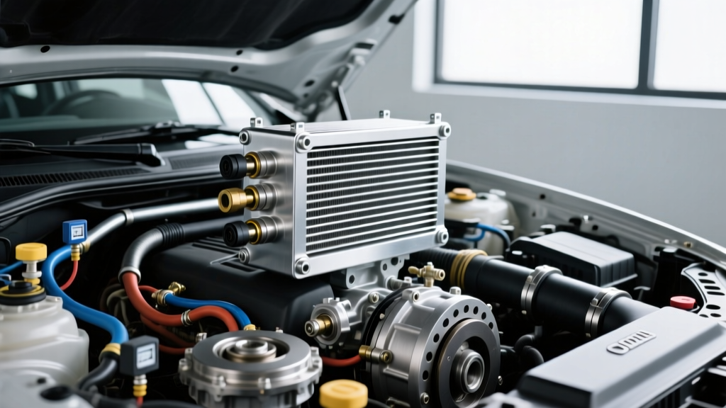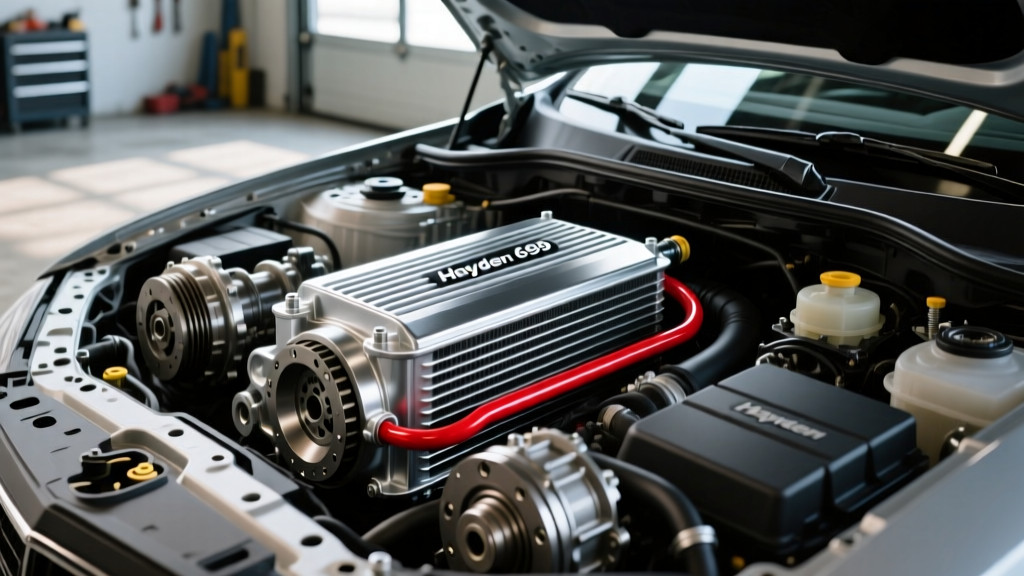
Introduction to the 5R110W Cooling Architecture
The Ford 6.0L Powerstroke, produced from 2003 to 2007, is paired with the robust 5R110W TorqShift automatic transmission. While the 5R110W is capable of handling immense torque, it generates significant thermal energy, particularly during heavy towing or sled pulling. Managing this heat is the primary function of the transmission cooling system. As of 2026, maintaining and upgrading this system is more critical than ever, as aging OEM components succumb to decades of heat cycling and environmental exposure. Understanding the exact fluid routing is the first step toward effective diagnostics and performance upgrades.
When technicians and DIY enthusiasts search for a reliable 6.0 powerstroke transmission cooler lines diagram, they often encounter conflicting information regarding the auxiliary cooler routing, the factory radiator integration, and the specific line sizes required for aftermarket upgrades. This technical deep-dive will decode the factory routing, identify common failure points, and provide actionable data for upgrading your 5R110W cooling circuit.
Decoding the 6.0 Powerstroke Transmission Cooler Lines Diagram
The factory cooling system for the 6.0L Powerstroke relies on a multi-stage heat exchange process. Unlike simpler setups that route fluid directly to a front-mounted cooler, the 5R110W utilizes the factory radiator as the primary heat sink, supplemented by an auxiliary air-to-oil cooler on specific configurations and upfitted models.
Hot Side vs. Cold Side Routing
To properly install an aftermarket cooler or perform a flush, you must correctly identify the hot and cold sides of the circuit. Misrouting an auxiliary cooler can lead to catastrophic transmission failure due to the 5R110W internal thermal bypass valve malfunctioning.
- Transmission Out (Hot Side): Fluid exits the rear fitting on the transmission case. Under heavy load, this fluid can reach 210°F to 230°F. It travels forward along the passenger side frame rail via a 1/2-inch steel line.
- Radiator In: The hot fluid enters the bottom tank of the factory radiator, passing through an internal tubular heat exchanger submerged in the engine coolant.
- Radiator Out: Fluid exits the radiator, typically dropping in temperature by 15°F to 25°F depending on engine coolant temps.
- Auxiliary Cooler Routing: From the radiator, the fluid routes to the frame-mounted auxiliary cooler (if equipped) or directly back to the transmission.
- Transmission In (Cold Side): The cooled fluid returns to the front fitting on the transmission case, where it passes through the lube valve and cooler bypass valve before lubricating the clutch packs and torque converter.
The Factory Radiator Integration
The internal radiator cooler acts as both a cooler and a warmer. During cold starts, the 5R110W requires rapid warming to achieve optimal fluid viscosity and torque converter lockup. The engine coolant heats the transmission fluid until it reaches operating temperature. However, when towing heavy loads in summer months, the engine coolant itself can exceed 210°F, severely limiting the radiator's ability to shed transmission heat. This is precisely why deciphering the 6.0 powerstroke transmission cooler lines diagram is vital for installing a standalone auxiliary cooler bypass.
Common Failure Modes in OEM Cooler Lines
The OEM steel lines and rubber hose segments on the 6.0L Powerstroke are notorious for specific failure modes as these trucks age. Identifying these issues early can prevent a total loss of the 17.5-quart MERCON LV fluid capacity, which would result in immediate clutch pack destruction.
- Galvanic Corrosion and Frame Rub: The steel lines are secured to the frame rail using rubber-insulated clamps. Over time, the rubber degrades, allowing the steel line to rub against the frame. Combined with road salt and moisture, this creates a deep groove that eventually bursts under the 40-60 PSI operating pressure of the 5R110W.
- Plastic Quick-Connect Degradation: The transition points between the steel lines and the rubber hoses utilize plastic quick-disconnect fittings. Engine bay heat cycling causes these plastic collars to become extremely brittle. Attempting to remove them without a specialized quick-connect release tool almost guarantees they will shatter, requiring a complete line replacement.
- Rubber Hose Swelling: The OEM rubber hoses are not always rated for the continuous high-temperature synthetic fluid (MERCON SP/LV). Internal swelling can restrict flow, mimicking a clogged cooler and triggering the P0218 transmission over-temperature code.
Upgrading to an Auxiliary Cooler: Bypass and Integration
For trucks used for heavy towing, bypassing the factory radiator's internal cooler and routing the fluid directly to a high-capacity stacked-plate auxiliary cooler is the gold standard. This eliminates the thermal ceiling imposed by hot engine coolant. According to data shared by diesel powertrain specialists on the Ford-Trucks 6.0L Powerstroke Forum, a properly sized standalone cooler can drop transmission temperatures by up to 40°F under sustained grade loads.
Required Parts and Torque Specifications
When executing the bypass and installing a heavy-duty cooler like the Derale Hyper-Cool or Hayden Rapid-Cool series, precision in assembly is required. Below is the critical data table for your installation.
| Component / Task | Part Number / Spec | Torque / Measurement |
|---|---|---|
| Transmission Case Fitting (Flare Nut) | OEM 5R110W Flare | 22 lb-ft |
| Auxiliary Cooler Mount Bracket | Derale 13012 Universal | 15 lb-ft (M8 bolts) |
| AN-8 Hose Clamp (Push-Lock) | Earl's 991808ERL | Hand tight + 1/4 turn |
| Transmission Pan Drain Plug | OEM Metric Bolt | 12 lb-ft |
| Cooler Line to Frame Bracket | 5/16-inch Stainless Bolt | 18 lb-ft |
When selecting your cooler, opt for a stacked-plate design over a tube-and-fin design. Stacked-plate coolers, such as those documented in the Derale Performance Transmission Coolers catalog, offer a 30% increase in heat dissipation surface area and are far less susceptible to clogging from debris due to their larger internal fluid passages.
Flushing the 5R110W Cooler Circuit
If your transmission has suffered a failure, or if you are replacing degraded lines, flushing the cooler circuit is mandatory. The 5R110W torque converter and cooler lines can trap metallic debris and clutch material. Never use high-pressure shop air directly on the cooler lines. The internal radiator tank and auxiliary cooler fins can easily rupture under unregulated shop air (which often exceeds 120 PSI).
Expert Diagnostic Tip: Always use a dedicated transmission cooler flusher machine that utilizes pulsating solvent and regulated air. If a machine is unavailable, use a regulated air compressor set to a maximum of 50 PSI, combined with a chemical cooler flush solvent, pushing the fluid out in the reverse direction of normal flow to dislodge trapped particulates.
Ensure you are refilling the system with the correct fluid. While early 6.0L Powerstrokes called for MERCON SP, Ford has officially superseded this with MERCON LV. Always consult the latest Motorcraft Official Fluid Specifications to ensure compatibility, as mixing SP and LV can cause friction modifier conflicts and torque converter shudder.
Expert Diagnostics: Flow Testing the Cooler Lines
One of the most overlooked procedures when diagnosing 5R110W overheating is the cooler flow test. A restriction in the lines, a collapsed internal hose, or a stuck thermal bypass valve will starve the transmission of lubrication and cooling. The 5R110W requires a minimum flow rate to maintain clutch pack integrity.
Step-by-Step Flow Test Procedure
- Disconnect the return line (cold side) at the transmission case fitting.
- Attach a length of clean 1/2-inch ID rubber hose to the disconnected line and route it into a calibrated 1-gallon collection jug.
- Start the engine and let it idle in Park. Do not rev the engine.
- Measure the volume of fluid collected over exactly 15 seconds.
- Multiply the collected volume by 4 to determine the Gallons Per Minute (GPM) flow rate.
Target Specification: The 5R110W should produce a minimum of 1.5 to 2.0 GPM at idle. If your flow rate is below 1.0 GPM, you have a severe restriction in the cooler lines, a clogged auxiliary cooler, or the internal transmission lube valve is failing to direct fluid to the cooler circuit. Addressing this flow restriction immediately is the difference between a simple line repair and a $4,000 transmission rebuild.
Conclusion
Mastering the 6.0 powerstroke transmission cooler lines diagram is not just about knowing which hose goes where; it is about understanding the thermal dynamics of the 5R110W TorqShift transmission. By recognizing the inherent weaknesses of the OEM steel lines and plastic quick-connects, and by upgrading to a high-flow stacked-plate auxiliary cooler with proper bypass routing, you can ensure your 6.0L Powerstroke remains reliable under the most demanding towing conditions. Always adhere to precise torque specifications and validate your work with a quantitative flow test to guarantee optimal transmission longevity.