System Overview: The 6R80 TR Sensor Circuit Architecture
As we survey the aging North American truck fleet in 2026, the 2016 F150 transmission range sensor and its associated wiring harness remain a critical focal point for preventive maintenance. The 2016 model year predominantly features the robust ZF-derived 6R80 6-speed automatic transmission. While the internal mechanicals of the 6R80 are notoriously durable, the external electronic interfaces—specifically the Transmission Range (TR) sensor circuit—are highly susceptible to environmental degradation.
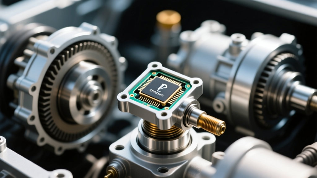
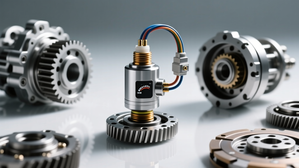
The TR sensor (often referred to as the neutral safety switch or manual lever position sensor) is a Hall-effect device mounted externally on the driver’s side of the transmission case, directly over the manual shift shaft. It communicates the gear selector position (Park, Reverse, Neutral, Drive, etc.) to the Powertrain Control Module (PCM). This data dictates the starter enable relay logic, reverse lamp illumination, and shift scheduling. When owners experience no-crank conditions, erratic PRNDL dashboard displays, or harsh engagement shifts, the immediate instinct is to replace the $110 Motorcraft sensor. However, field data indicates that over 70% of P0705 (Transmission Range Sensor Circuit Malfunction) and P0708 codes stem from wiring harness chafing, connector corrosion, and pin fretting—not the sensor itself.
Pathology of Failure: Why Connectors and Wiring Degrade
Before diving into the preventive maintenance protocol, it is vital to understand the specific failure modes that plague the 2015–2017 F-150 platform. The undercarriage environment is brutal, and the TR sensor wiring is routed in a highly vulnerable zone.
1. Micro-Fretting and Pin Spread
The 6R80 transmission generates significant high-frequency harmonic vibrations. Over a decade of operation, these micro-vibrations transfer through the transmission case and into the TR sensor pigtail connector. This causes 'fretting'—a wear phenomenon where the male and female terminal pins rub against each other at a microscopic level, wearing away the tin or gold plating and exposing the base copper to oxidation. Concurrently, repeated thermal cycling (from -20°F winters to 200°F+ transmission case temperatures) causes the plastic connector housing to expand and contract, leading to 'pin spread' where the female terminals lose their gripping tension on the male sensor pins.
2. Harness Chafing at the Crossmember and Pan
The wiring loom exiting the TR sensor must navigate a tight gap between the aluminum transmission pan, the steel crossmember, and the shift cable bracket. Factory split-loom and electrical tape degrade rapidly when exposed to road salt, UV radiation, and high-pressure car washes. Once the outer sheath is compromised, the 5V reference and signal return wires rub directly against the aluminum case, eventually wearing through the insulation and causing a dead short to ground. This instantly triggers a P0706 (Transmission Range Sensor Circuit Range/Performance) code and can backfeed voltage into the PCM, risking module damage.
3. Capillary Moisture Wicking
If the secondary weather seal on the TR sensor connector is cracked or missing, water ingress occurs. More insidiously, moisture can wick up the inside of the wire insulation via capillary action, traveling inches or even feet up the harness toward the PCM firewall pass-through. This results in green copper oxide buildup deep inside the harness, creating high-resistance voltage drops that mimic a failing sensor.
Technician's Note: Never use standard silicone RTV to seal a transmission electrical connector. Silicone off-gases acetic acid during curing, which aggressively corrodes copper terminals. Always use sensor-safe, electrically inert dielectric compounds.
Preventive Intervention Protocol: Step-by-Step Maintenance
To ensure the longevity of your 2016 F-150's 6R80 transmission electronics, perform the following preventive maintenance procedure every 60,000 miles or 4 years, whichever comes first.
Phase 1: Harness Routing and Loom Inspection
- Vehicle Elevation: Safely lift the truck on a hoist or jack stands. Remove the driver-side inner fender liner for top-down access to the TR sensor, or work from underneath with a high-lumen inspection light.
- Loom Removal: Carefully cut away the factory corrugated split-loom and degraded friction tape using a seam ripper. Do not use a razor blade, as the risk of slicing the 20-gauge signal wires is high.
- Inspection: Trace the harness from the sensor connector back to the main case connector (C167). Look for flattened wires, copper show-through, or brittle insulation.
- Re-wrapping: Wrap the bare harness in Tesa 51036 PET cloth tape (the OEM standard for high-heat, abrasion-resistant harness wrapping). Follow this with a new piece of nylon split-loom, securing it with zip-ties placed at least 2 inches away from any sharp metal edges.
Phase 2: Connector Deoxidation and Pin Tensioning
- Disconnect: Press the locking tab and pull the connector. Inspect the silicone weather seal. If it is torn, flattened, or missing, the connector must be replaced.
- Chemical Cleaning: Spray both the male sensor pins and the female connector terminals with DeoxIT D5 contact cleaner. This solution dissolves copper oxide and leaves a protective molecular film.
- Tension Check: Using a precision pin gauge (or a properly sized sewing needle), test the drag on each female terminal. If a pin slides in with zero resistance, the terminal is 'spread' and must be extracted and replaced, or the entire pigtail must be spliced in.
- Sealing: Pack the female connector cavity with Nyogel 760G dielectric grease. This specific fluorocarbon grease is engineered for automotive sensors; it prevents moisture ingress without interfering with low-current 5V signal transmission.
Diagnostic Benchmarks: 6R80 TR Sensor Pinout & Voltage
When performing preventive maintenance, it is best practice to verify the electrical integrity of the circuit using a digital multimeter (DMM) with the key on, engine off (KOEO). Back-probe the connector to read live values.
| Pin | Circuit Function | Expected KOEO Voltage | Common Failure Symptom |
|---|---|---|---|
| 1 | 5V Reference (VREF) | 4.8V - 5.1V | Short to ground (P0705/P0708) |
| 2 | Signal Return A | Varies by Gear (Multiplex) | Open circuit (No PRNDL display) |
| 3 | Signal Return B | Varies by Gear (Multiplex) | Erratic shift scheduling |
| 4 | Signal Return C | Varies by Gear (Multiplex) | Starter enable failure (No crank) |
| 5 | Signal Return D | Varies by Gear (Multiplex) | Reverse lamps inoperative |
| 6 | Sensor Ground (SIG RTN) | < 0.1V (Voltage Drop Test) | High resistance causes skewed VREF |
Note: The 6R80 uses a multiplexed signal architecture. Instead of a dedicated wire for every single gear, the PCM reads a unique voltage combination across the signal return pins to determine the exact manual lever position. A voltage drop on the ground circuit (Pin 6) exceeding 0.1V will shift the entire multiplex matrix, causing the PCM to misread 'Park' as 'Reverse' or 'Neutral'.
Repair vs. Replace: Splicing Protocols and Part Numbers
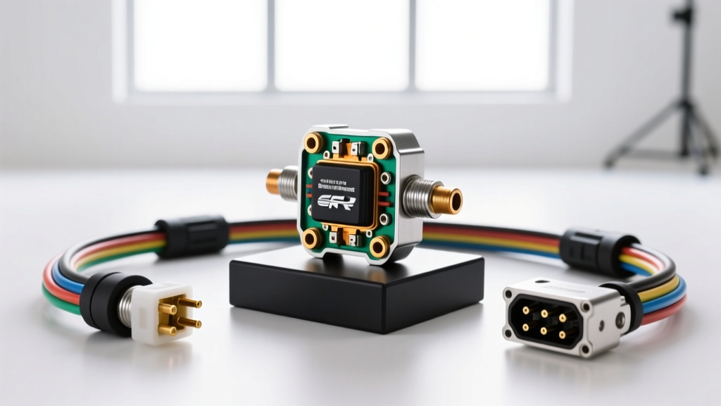
If your inspection reveals severe green corrosion inside the wire insulation, or if the female pins are irreparably spread, cleaning will not suffice. You must replace the pigtail harness.
The Wrong Way: Twist-and-Tape
Never use twist-on wire connectors, crimp-only butt splices, or standard electrical tape for undercarriage transmission wiring. These methods will fail within months due to thermal expansion and moisture.
The Right Way: Solder-Seal Splicing
Use Raychem SolderSleeves or marine-grade adhesive-lined heat shrink butt connectors. The process involves: 1. Stripping 3/8" of insulation. 2. Crimping the barrel. 3. Soldering the joint for maximum conductivity. 4. Applying heat to melt the internal polyamide adhesive, creating a 100% waterproof seal.
OEM Part Reference Guide
- TR Sensor Assembly: Motorcraft SW-7189 (Ford Part # BL3Z-7F247-A) - MSRP: ~$115
- Sensor Pigtail Connector: Motorcraft WPT-1246 (or equivalent 6-pin weatherpack) - MSRP: ~$35
- Mounting Bolt Torque Spec: 10 Nm (89 lb-in). Do not overtighten; the sensor housing is brittle composite plastic and will crack, allowing moisture into the Hall-effect chamber.
Final Thoughts on Fleet Longevity
Preventive maintenance on the 2016 F150 transmission range sensor wiring is a high-ROI investment. Spending 45 minutes and $20 on Tesa cloth tape, DeoxIT, and Nyogel 760G can easily prevent a $400 tow bill and a misdiagnosed PCM replacement. For more in-depth discussions on 6R80 electrical gremlins and community-tested wiring diagrams, technicians and owners frequently consult the Ford F-150 Forum's 13th Generation Technical Subforum. Additionally, understanding the exact trigger conditions for transmission codes via resources like OBD-Codes P0705 Diagnostics can save hours of diagnostic guesswork. Always source your replacement pigtails and sensors directly from Motorcraft Official Parts to avoid the premature failure rates associated with cheap aftermarket knock-offs.