What Is a Pressure Cylinder and Why Does It Matter?
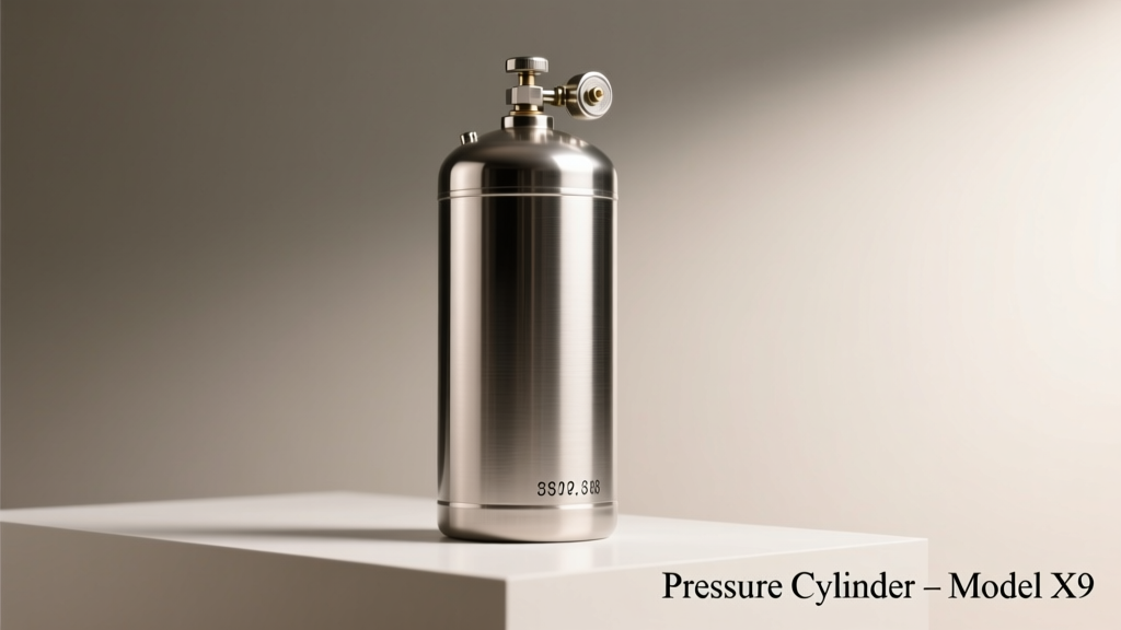
A pressure cylinder is a closed, pressure-retaining vessel engineered to safely contain gases or liquids at pressures substantially higher than ambient atmospheric pressure. Unlike simple storage tanks, pressure cylinders are subject to stringent mechanical, thermal, and regulatory constraints that govern geometry, material grade, fabrication method, inspection frequency, and service life. In industrial settings—from ammonia synthesis plants to medical oxygen delivery systems—the failure of a pressure cylinder can result in catastrophic rupture, fire, or toxic release. According to the U.S. Chemical Safety and Hazard Investigation Board (CSB), 12% of major process safety incidents between 2015–2022 involved pressure vessel failures directly attributable to noncompliant cylinder design or overdue requalification. This article details the engineering fundamentals, regulatory framework, dimensional specifications, and real-world performance benchmarks that define safe, reliable pressure cylinder operation.
Regulatory Framework and Design Standards
The global standard for pressure cylinder design is the ASME Boiler and Pressure Vessel Code (BPVC), specifically Section VIII, Division 1 for most welded and forged vessels, and Division 2 for high-risk or high-pressure applications (e.g., >10,000 psi). In Europe, EN 13445 governs unfired pressure vessels, while ISO 9809-1:2019 applies to seamless steel gas cylinders used for transport. Regulatory compliance is not optional: OSHA 29 CFR 1910.109 mandates that all pressure vessels operating above 15 psi gauge pressure must be constructed, inspected, and maintained per an ASME-stamped code.
ASME Section VIII Key Requirements
Section VIII sets minimum requirements for materials, design stress values, joint efficiency, and testing. For example, the maximum allowable working pressure (MAWP) must be calculated using the formula: MAWP = (2 × S × E × t) / (D − 0.2 × t), where S is the maximum allowable stress value (e.g., 16,600 psi for SA-516 Gr. 70 at 300°F), E is joint efficiency (0.85 for Type 1 welded joints), t is nominal wall thickness in inches, and D is inside diameter in inches. A 36-inch ID carbon steel vessel with 1.125-inch wall thickness and full radiographic examination (E = 1.0) yields an MAWP of 472 psi at design temperature—verified during third-party review by authorized inspectors such as those certified by the National Board of Boiler and Pressure Vessel Inspectors.
International Harmonization Efforts
While ASME and EN standards differ in calculation methodology, the 2021 revision of PED 2014/68/EU introduced Annex I alignment with ASME’s fatigue analysis provisions. Japan’s JIS B 8243:2020 also references ASME Section VIII for high-temperature hydrogen service. Notably, Luxfer Gas Cylinders’ 10L aluminum Type 3 composite cylinders (model AL-10) meet both DOT-SP 16312 (U.S.) and TPED 2010/35/EU certification—enabling cross-border deployment in LNG fueling infrastructure across California and the Netherlands.
Material Selection: Strength, Corrosion Resistance, and Temperature Limits
Material choice directly determines pressure capacity, weight, service life, and cost. Carbon steels dominate low-to-medium pressure applications due to cost-effectiveness and weldability; stainless steels and aluminum alloys serve niche roles requiring corrosion resistance or weight reduction. All materials must conform to ASTM or ASME material specifications—with traceable mill test reports required for each heat lot.
Carbon Steel: SA-516 Grade 70 Dominates Industrial Use
SA-516 Gr. 70 remains the most widely specified plate material for stationary pressure cylinders. Its minimum yield strength is 38,000 psi, tensile strength ranges from 70,000–90,000 psi, and Charpy V-notch impact energy at −20°F exceeds 20 ft·lb. Worthington Industries’ 120-gallon propane storage cylinders (model W120P) use 0.375-inch thick SA-516 Gr. 70 plates, rated for 250 psi MAWP and certified to ASME Section VIII, Div. 1. These cylinders undergo ultrasonic testing (UT) per ASTM A435 and post-weld heat treatment at 1100°F for 1 hour per inch of thickness to relieve residual stresses.
Stainless Steel and Aluminum Alloys for Specialized Environments
For aggressive chemical service, SA-240 316L stainless steel offers superior pitting resistance (PREN ≥ 25) and maintains strength up to 1500°F. Nippon Steel’s NS 316L-HR cylinders—used in semiconductor fab tool purge gas systems—achieve wall thicknesses as low as 0.1875 inches while sustaining 1000 psi at 200°C. In contrast, 6061-T6 aluminum (used in portable SCBA cylinders) provides a 40% weight reduction versus steel but limits MAWP to 4500 psi due to lower yield strength (40,000 psi). Luxfer’s 6.8L aluminum Type 2 cylinder (AL-6.8) weighs only 11.2 kg yet delivers 300 bar (4350 psi) service pressure—validated per ISO 9809-1 Annex C burst tests showing minimum 4.5× design pressure failure threshold.
Dimensional Specifications and Wall Thickness Calculations
Wall thickness is never arbitrary—it is derived from internal pressure, geometry, material properties, and safety margins. ASME Section VIII mandates a minimum design margin of 3.5× for brittle fracture prevention and 4.0× for fatigue-limited service. Cylindrical shells experience two principal stress components: hoop stress (circumferential) and longitudinal stress (axial), with hoop stress being twice as large. Therefore, wall thickness is primarily governed by hoop stress criteria.
Consider a horizontal cylindrical vessel with an inside diameter of 48 inches, designed for 300 psi MAWP at 250°F, fabricated from SA-516 Gr. 70 (S = 16,600 psi), with Type 1 welded joints (E = 0.85). Using the standard hoop stress equation:
- Hoop stress: σh = P × D / (2 × t)
- Rearranged for t: t = P × D / (2 × S × E)
- t = (300 psi × 48 in) / (2 × 16,600 psi × 0.85) = 0.507 inches
ASME requires adding corrosion allowance (typically 0.125 in for mild environments) and mill tolerance (up to +0.125 in / −0.000 in for plates per ASTM A20). Thus, the ordered plate thickness becomes 0.75 inches. This matches actual production specs for Baker Hughes’ Model BH-48300 separator drums—widely deployed in Permian Basin natural gas processing facilities.
| Cylinder Type | OD (in) | Wall Thickness (in) | MAWP (psi) | Design Temp (°F) | Material | Manufacturer |
|---|---|---|---|---|---|---|
| Vertical Receiver | 30.0 | 0.375 | 200 | 350 | SA-516 Gr. 70 | Worthington W30V |
| High-Pressure H2 | 9.25 | 1.000 | 10,000 | 150 | SA-372 Gr. J | Quest Integrity QH2-10K |
| LNG Transport | 60.0 | 0.625 | 250 | −260 | SA-612 Class 1 | Kawasaki Heavy Industries K-LNG60 |
| Medical Oxygen | 8.5 | 0.250 | 2216 | 70 | SA-204 Gr. A | Luxfer M10-2216 |
Manufacturing Processes and Quality Assurance
Three primary fabrication methods dominate pressure cylinder production: seamless extrusion (for small-diameter, high-pressure units), hot-spinning (for hemispherical heads), and roll-and-weld (for large-diameter shells). Seamless cylinders eliminate welds entirely—critical for hydrogen service where atomic diffusion can cause embrittlement. Hot-spinning uses CNC-controlled rollers to shape heated plate into dished ends meeting ASME UG-32(e) tolerances: no deviation greater than 1.25% of crown radius. Roll-and-weld processes require full-penetration groove welds qualified per ASME Section IX, with essential variables documented in Welding Procedure Specifications (WPS).
Every ASME-stamped cylinder bears a permanent nameplate listing: manufacturer name, serial number, design pressure and temperature, material specification, year built, and National Board number. The stamp itself—either “U”, “UM”, or “UV”—indicates compliance level. A “U” stamp signifies Division 1 compliance; “UV” denotes Division 2 with additional fatigue analysis. Third-party inspection is mandatory: AI (Authorized Inspector) firms like TÜV Rheinland or Bureau Veritas conduct surveillance during fabrication, verify NDE results, and witness hydrostatic tests.
Non-Destructive Examination Protocols
ASME mandates specific NDE methods based on thickness and service. For vessels >1.5 inches thick, 100% radiographic testing (RT) of circumferential and longitudinal welds is required per Article 2, Table UW-51. For thinner walls, ultrasonic testing (UT) may substitute per UW-53. Magnetic particle testing (MT) inspects nozzle-to-shell attachments, while dye penetrant (PT) validates surface integrity of forged flanges. At Air Products’ Port Arthur facility, every 120-inch diameter hydrogen buffer tank undergoes phased-array UT scanning at 0.020-inch resolution, detecting planar flaws as small as 0.04 inches in length.
Hydrostatic Testing and Requalification Procedures
Before commissioning, each pressure cylinder must pass hydrostatic testing at 1.3× MAWP per ASME UG-99. Test duration is minimum 30 minutes at stabilized pressure, with no visible distortion or leakage observed. Test fluid must be water with ≤25 ppm chloride content to prevent stress corrosion cracking in stainless units. Pressure is monitored via calibrated deadweight testers traceable to NIST standards—uncertainty ≤0.05% FS. After test, cylinders receive a hydrotest date stamp and entry in the National Board Database (NB-237 form).
Requalification intervals depend on service and jurisdiction. DOT-regulated transport cylinders require retesting every 5 or 10 years depending on type: aluminum cylinders (e.g., Luxfer AL-20) every 5 years; seamless steel (e.g., Worthington WS-45) every 10 years. Visual inspection alone is insufficient—each requalification includes volumetric expansion measurement using water jacket apparatus per ISO 6406. A 45L steel cylinder filled to 200 bar must demonstrate elastic expansion ≤10% of total volume; exceeding this triggers rejection. In 2023, over 2.1 million cylinders were rejected during U.S. requalification due to wall thinning beyond 10% original thickness—a primary cause linked to internal corrosion in CO₂ service.
Real-World Failure Modes and Mitigation Strategies
Common failure modes include hydrogen-induced cracking (HIC) in sour service, chloride stress corrosion cracking (CSCC) in coastal refineries, and fatigue cracking at nozzle junctions under cyclic thermal loading. Mitigation begins with material selection: NACE MR0175/ISO 15156-compliant SA-516 Gr. 70N (normalized) reduces HIC susceptibility by 70% versus standard Gr. 70. For CSCC, duplex stainless steels like UNS S32205 (with PREN ≥ 34) replace 316L in desalination plant brine cylinders. Fatigue life extension is achieved via finite element analysis (FEA)-driven fillet radius optimization—increasing root radius from 0.125 in to 0.375 in at a 6-inch nozzle reduces peak stress by 42%, as validated in Siemens Energy’s F-class turbine lube oil reservoirs.
Emerging Trends and Future-Ready Designs
Industry is shifting toward digital twin integration, predictive maintenance, and advanced materials. Baker Hughes’ Digital Twin Platform ingests real-time strain gauge and temperature sensor data from pressure cylinders in offshore platforms, forecasting remaining useful life (RUL) with ±8% accuracy at 90% confidence. Additive manufacturing is enabling topology-optimized supports: Oak Ridge National Laboratory demonstrated a 3D-printed Inconel 718 mounting bracket for a 5000-psi helium cylinder that reduced mass by 37% without compromising stiffness.
Fuel cell mobility drives innovation in lightweight composites. Toyota’s Mirai uses Type IV carbon-fiber-reinforced polymer (CFRP) cylinders rated to 70 MPa (10,153 psi)—achieving 5.7 wt% hydrogen storage density, surpassing DOE 2025 targets. These cylinders feature thermoplastic liners (polyamide 6) bonded to 300 GPa modulus carbon fiber wraps, with burst pressures verified at 15,000 psi during qualification per SAE J2579. Meanwhile, regulations evolve: the 2024 ASME BPVC Addenda introduces mandatory fracture mechanics assessment for vessels operating below the ductile-to-brittle transition temperature—closing a long-standing gap in cryogenic LNG applications.
Pressure cylinders are foundational—not peripheral—to system safety and operational continuity. Their engineering reflects decades of accumulated failure analysis, materials science advancement, and regulatory refinement. From a 10-liter medical oxygen bottle stamped with Luxfer’s “DOT 3AL” mark to a 120-ton hydrogen storage sphere at a green ammonia plant in Saudi Arabia’s NEOM city, consistent adherence to dimensional precision, metallurgical control, and procedural rigor prevents catastrophe. Engineers specifying these components must treat every parameter—not just MAWP—as a non-negotiable constraint. A 0.015-inch wall thickness variance, an unreported mill heat number, or a skipped hydrotest interval isn’t administrative oversight—it’s a latent defect waiting for the right combination of temperature, pressure, and time to propagate. That reality underscores why pressure cylinder engineering remains one of the most consequential disciplines in mechanical design.
Manufacturers continue raising the bar: Worthington’s 2023 W-Series now incorporates laser-ultrasonic thickness mapping pre- and post-hydrotest to quantify localized thinning with ±0.002-inch resolution. Nippon Steel’s newly launched NS-HYPER line features grain-refined 304LN stainless with 20% higher creep rupture strength at 700°C—targeting next-generation supercritical CO₂ power cycles. These developments reinforce a core principle: pressure containment is not static technology. It evolves daily—in laboratories, on shop floors, and in the field—driven by data, discipline, and uncompromising standards.
Designers, inspectors, and operators share equal responsibility in this ecosystem. No amount of computational modeling replaces hands-on verification of weld profiles, no database supplants visual inspection for pitting under insulation, and no certification substitutes for understanding the physics behind the formula. When a pressure cylinder operates flawlessly for 30 years, it does so because thousands of decisions—material selection, thickness calculation, NDE method, test pressure, requalification schedule—were executed correctly, consistently, and without exception.
The cylinder itself is silent. But its specifications speak volumes—about material science, regulatory maturity, manufacturing fidelity, and human accountability. That silence is earned, not assumed.
Standards bodies update requirements annually—not to complicate work, but to encode hard-won lessons. In 2022 alone, ASME issued 14 revisions to Section VIII addressing hydrogen compatibility, additive manufacturing validation, and seismic anchorage for vertical vessels. Each change reflects incident investigations, accelerated testing data, or field performance analytics. Ignoring these updates doesn’t save time—it multiplies risk.
Ultimately, the pressure cylinder is a contract: between engineer and operator, between manufacturer and end user, between present action and future safety. Its geometry is precise, its materials traceable, its testing verifiable. There is no room for approximation—only exactness, evidence, and accountability.
That exactness begins with understanding that a cylinder is never just a container. It is a boundary—one that separates controlled energy from uncontrolled consequence. And boundaries, when properly engineered, do not merely hold pressure. They hold promise.
Whether supplying oxygen to a neonatal ICU, storing hydrogen for zero-emission trucks, or buffering steam in a nuclear plant, the cylinder performs its duty invisibly—until it doesn’t. Which is precisely why its engineering demands relentless attention to detail, unwavering adherence to standards, and profound respect for the forces it contains.
This isn’t theoretical. It’s measured in psi, verified in microns, logged in NB-237 forms, and proven in burst tests at independent labs like Southwest Research Institute’s Pressure Technology Division—where every cylinder undergoes destructive validation before commercial release. That commitment to empirical proof defines the discipline—and explains why, after more than a century of evolution, the pressure cylinder remains among the most trusted mechanical components ever devised.