Introduction: Beyond the Sensor Itself
Modern automatic transmissions rely on a symphony of electronic inputs to dictate shift timing, torque converter clutch (TCC) application, and line pressure modulation. Among the most critical of these inputs are the Input Speed Sensor (ISS) and Output Speed Sensor (OSS). When a vehicle exhibits erratic shifting, limp-mode activation, or a dead speedometer, the immediate assumption is often a failed internal component. However, when diagnosing the signs of a bad transmission speed sensor, experienced drivetrain specialists know that up to 60% of these failures are not the sensor itself, but rather the wiring harness and connector interfaces.
As of 2026, with the widespread integration of 10-speed automatics like the GM 10L90 and Ford 10R80, the undercarriage environment is harsher than ever. Heat cycling, road debris, and transmission fluid leaks degrade electrical connections long before the solid-state sensor fails. This preventive maintenance guide focuses exclusively on the wiring and connector ecosystems of transmission speed sensors, providing actionable diagnostics, repair protocols, and torque specifications to ensure long-term reliability.
Anatomy of the Speed Sensor Circuit
Before inspecting wiring, it is vital to understand the circuit architecture. Older vehicles utilized Variable Reluctance (VR) sensors, which generated an AC voltage signal via a magnetic pickup. Today, nearly all modern transmissions—including the ZF 8HP series and GM 6L80/8L90 families—utilize Hall-Effect or Magneto-Resistive (MR) sensors.
The 3-Wire Digital Circuit
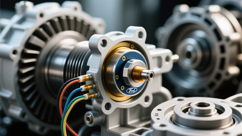
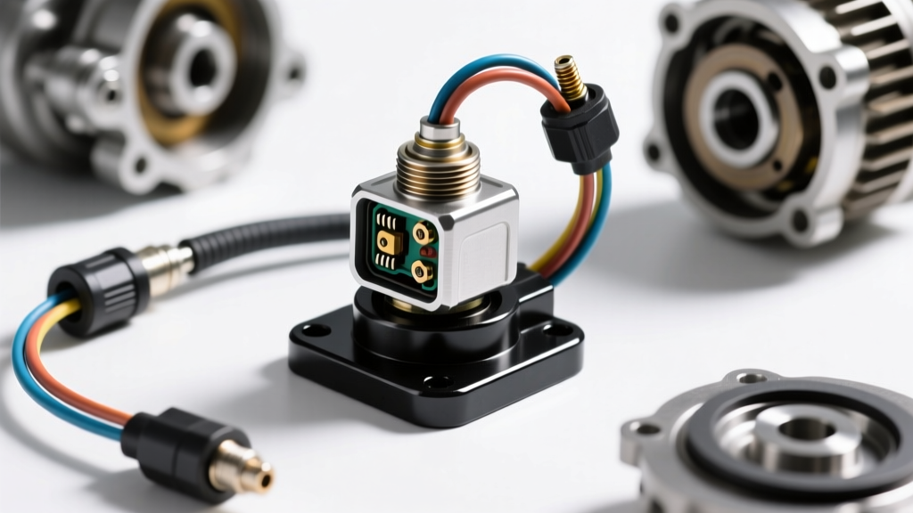
Modern MR speed sensors require three dedicated wires routed from the Transmission Control Module (TCM):
- 5-Volt Reference (5V Ref): Supplies a precise 4.9V to 5.1V DC power feed from the TCM.
- Low Reference (Ground): Provides a dedicated signal ground back to the TCM, isolated from chassis ground to prevent noise.
- Signal Circuit: Carries a digital square-wave pulse (typically toggling between 0V and 5V) back to the TCM as the reluctor ring teeth pass the sensor.
Because these signals operate at high frequencies and low voltages, the wiring is highly susceptible to electromagnetic interference (EMI). Consequently, OEMs route these circuits using Shielded Twisted Pair (STP) wiring. Compromising this shielding during a sloppy repair is a primary cause of recurring P0715 or P0720 diagnostic trouble codes (DTCs).
Identifying the Signs of a Bad Transmission Speed Sensor vs. Wiring Faults
Differentiating between a dead sensor and a compromised connector requires a systematic approach. The table below outlines how to interpret common symptoms and DTCs to isolate the root cause.
| Symptom / DTC | Wiring / Connector Fault Indicator | Internal Sensor Fault Indicator |
|---|---|---|
| P0715 / P0720 (Input/Output Circuit Malfunction) | Code sets intermittently over bumps or during high-vibration driving. 5V Ref reads 0V at the connector. | Code is hard-set and continuous. 5V Ref is present at the connector, but no signal is generated when the shaft is spun. |
| P0716 / P0721 (Range/Performance) | Signal drops out momentarily. Oscilloscope shows 'glitches' or dropped teeth in the square wave pattern. | Signal is completely absent or stuck at a flat 5V / 0V state regardless of shaft rotation. |
| Harsh 2-3 Upshifts & TCC Shudder | Corrosion or pin-spread in the connector cavity causing micro-second signal delays. | Sensor is physically cracked or contaminated with metallic debris on the magnetic tip. |
| TCM Limp Mode (Default Gear) | Complete harness chafing against the exhaust or bellhousing, shorting the 5V Ref to ground. | Internal Hall-effect chip burnout due to voltage spike or extreme heat. |
Preventive Maintenance: Connector and Harness Care
Preventive maintenance for transmission electronics is rarely discussed in standard service intervals, yet it is critical for longevity. The connection point where the chassis harness mates to the transmission case or the internal mechatronic sleeve is the most vulnerable failure point.
The Pin Drag Test
Micro-fretting corrosion and loss of terminal tension are silent killers of speed sensor signals. During any transmission service or sensor replacement, perform a 'pin drag test'. Using a dummy test pin or a known-good male terminal, insert it into the female connector cavity. You should feel a distinct, crisp drag. If the pin slides in and out with zero resistance, the female terminal is stretched. Do not attempt to squeeze the terminal with pliers. Replace the pigtail immediately to prevent intermittent signal loss.
Dielectric Grease Application
Moisture ingress leads to galvanic corrosion between the male and female terminals. According to guidelines published by the Society of Automotive Engineers (SAE), applying a high-quality, copper-compatible dielectric grease (such as Nyogel 760G or standard silicone dielectric compound) to the connector cavity is mandatory. This displaces moisture and prevents oxygen from reaching the metal contacts. Apply a small dab to the female connector side before mating; avoid over-packing, which can cause hydro-lock and prevent the connector from fully seating.
Diagnostic Testing: Multimeter and Oscilloscope Protocols
When the signs of a bad transmission speed sensor point toward an electrical fault, guessing is not an option. You must verify the circuit integrity before condemning the component.
Step 1: Back-Probing the Connector
Never pierce the wire insulation with a test light or multimeter probe. Piercing creates a pathway for moisture to wick into the copper strands via capillary action, guaranteeing future corrosion. Instead, use dedicated T-pin back-probes to access the terminal from the rear of the connector while it is mated to the sensor.
Step 2: Voltage and Resistance Checks
- 5V Reference Check: Key On, Engine Off (KOEO). Measure between the 5V Ref pin and a known-good chassis ground. You must see exactly 4.9V to 5.1V. A reading of 0V indicates a short to ground in the harness or a fried TCM driver.
- Ground Circuit Integrity: Measure resistance between the sensor ground pin and the battery negative terminal. It should read less than 0.5 ohms. Anything higher indicates a corroded splice or a failing TCM ground.
- Signal Wire Continuity: With the battery disconnected, check for continuity between the sensor signal pin and the corresponding TCM pin. Look for infinite resistance (open circuit) or continuity to ground (short circuit).
Expert Tip: If you are diagnosing a ZF 8HP transmission (found in BMW, Audi, and Chrysler vehicles), the speed sensors are integrated directly into the mechatronic unit. Wiring faults here often stem from the infamous ZF sealing sleeve (adapter) where the external chassis harness plugs into the transmission case. Always inspect the sealing sleeve pins for fluid contamination, as capillary action can draw ATF directly into the TCM.
Repair Procedures: Pigtails, Torque Specs, and Routing
When a harness is chafed, melted, or the connector is melted, a proper repair requires OEM-grade materials and precise mechanical assembly.
Soldering vs. Crimping
While weather-pack crimpers are acceptable for quick fixes, the gold standard for transmission speed sensor wiring repair is rosin-core soldering sealed with adhesive-lined marine heat shrink (e.g., 3M MDT). The adhesive lining melts and flows into the wire strands, creating a watertight seal that prevents capillary wicking. When repairing Shielded Twisted Pair (STP) wiring, ensure the braided shield is reconnected and wrapped in copper foil tape to maintain EMI protection. For GM 6L80/6L90 applications, sourcing an OEM pigtail like the ACDelco PT2825 (OSS) or PT2826 (ISS) is highly recommended over generic aftermarket connectors to ensure proper pin tension and plastic resin quality.
Sensor Installation and Torque Specifications
Improper installation of the speed sensor into the transmission case can lead to physical damage or inaccurate air-gap readings. The sensor mounts via small M6 bolts, which are easily overtightened, cracking the plastic sensor housing and allowing ATF to enter the electronic cavity.
- GM 6L80 / 8L90 ISS & OSS Mounting Bolts: Torque to 11 Nm (97 lb-in). Do not exceed this spec.
- GM 4L60E VSS (Vehicle Speed Sensor): Torque the hold-down bolt to 16 Nm (12 lb-ft).
- ZF 8HP Internal Sensors: These are pressed into the mechatronic valve body and secured by the valve body separator plate. Torque the valve body Torx bolts in the OEM-specified spiral sequence to 8 Nm (71 lb-in).
Always apply a small amount of fresh, OEM-specified ATF to the sensor O-ring before installation to prevent rolling or pinching the seal against the aluminum case.
Conclusion
Recognizing the signs of a bad transmission speed sensor is only the first step in the diagnostic process. By shifting your focus to the wiring harness, connector integrity, and circuit shielding, you can eliminate the root cause of erratic shifting and TCM fault codes. Preventive maintenance—such as performing pin drag tests, applying dielectric grease, and utilizing adhesive-lined heat shrink during repairs—ensures that the digital signals governing your transmission remain pristine. Whether you are servicing a heavy-duty GM 10L90 or a precision ZF 8HP, treating the wiring with the same respect as the internal mechanical components is the hallmark of true drivetrain expertise.