The Anatomy of Speedometer Failure: ISS vs. OSS
When drivers experience a dead, bouncing, or erratic speedometer, the immediate culprit is often traced back to transmission speed sensor symptoms. In modern automotive engineering, the mechanical speedometer cable is a relic of the past. Today, your instrument panel cluster (IPC) relies entirely on digital data networks to display vehicle speed. Understanding how this data is generated, routed, and interpreted is the first step in performing a professional-grade diagnosis.
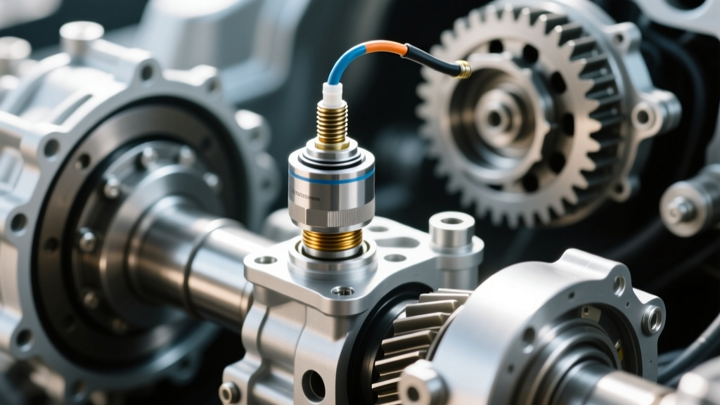
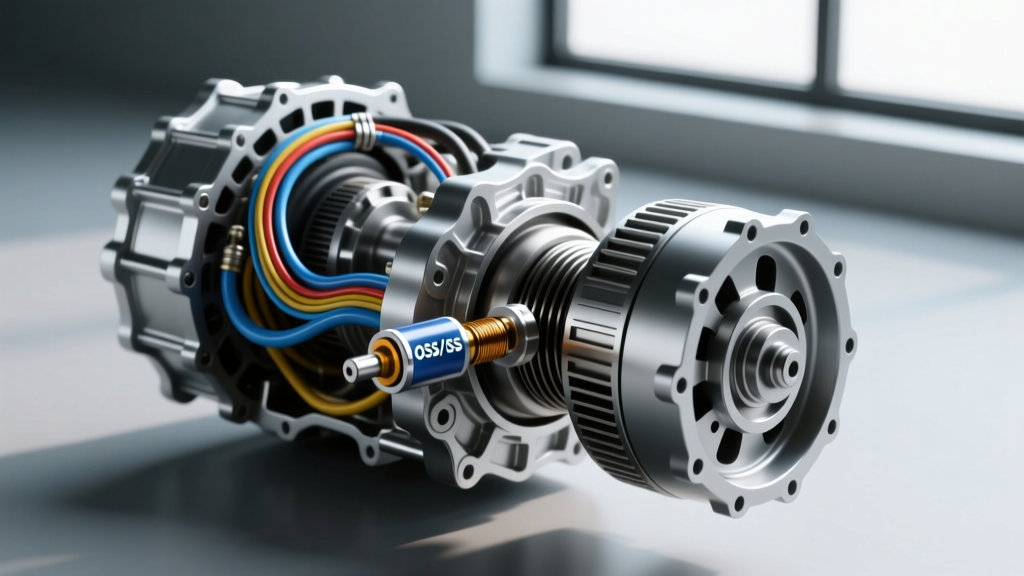
The transmission relies on two primary speed sensors: the Input Speed Sensor (ISS) and the Output Speed Sensor (OSS). The ISS monitors the rotational speed of the transmission's input shaft (turbine shaft), allowing the Transmission Control Module (TCM) to calculate clutch slip and manage shift timing. The OSS, however, monitors the output shaft or the park gear ring. It is the OSS signal that ultimately dictates your speedometer reading, cruise control operation, and electronic shift scheduling.
If the OSS fails or its signal degrades, the TCM loses its primary vehicle speed reference. According to SAE International diagnostic standards, a loss of the OSS signal forces the TCM into a fail-safe or 'limp-home' mode, simultaneously disabling the CAN-bus broadcast of vehicle speed to the instrument cluster. This results in a speedometer dropping to zero while the vehicle is in motion—one of the most alarming transmission speed sensor symptoms a driver can encounter.
Core Transmission Speed Sensor Symptoms & Diagnostic Trouble Codes
Identifying speedometer sensor issues requires looking beyond the dashboard gauge. A failing speed sensor triggers a cascade of electronic and mechanical anomalies across the vehicle's powertrain and chassis networks. Below are the primary symptoms and their corresponding OBD-II trouble codes:
- Erratic or Bouncing Speedometer Needle: Often caused by a degrading Variable Reluctance (VR) sensor picking up metallic debris on its magnetic tip, or a failing Hall-effect sensor dropping its square-wave signal.
- Harsh or Delayed Shifts: Without accurate OSS data, the TCM cannot calculate shift pressure algorithms. Line pressure defaults to maximum to prevent clutch burn-up, resulting in bone-jarring 1-2 and 2-3 shifts.
- Cruise Control Inoperability: The PCM/TCM will disable cruise control if it detects a variance between the OSS and the ABS wheel speed sensors.
- ABS and Traction Control Warnings: In vehicles where the TCM shares vehicle speed data with the Electronic Brake Control Module (EBCM) over the CAN-bus, an OSS failure can trigger false ABS interventions.
- Speedometer Reads Zero in Drive, Normal in Reverse: A classic symptom of a damaged OSS reluctor ring or a sensor installed with an incorrect air gap.
Common DTCs: P0720 (Output Speed Sensor Circuit Malfunction), P0722 (Output Speed Sensor No Signal), P0500 (Vehicle Speed Sensor 'A' Malfunction), and P0717 (Input Speed Sensor Circuit No Signal).
Technical Diagnostics: Pinout, Resistance, and Scope Testing
To accurately diagnose transmission speedometer sensor issues, technicians must identify the sensor topology. Older transmissions (like the early GM 4L60E) utilized 2-wire Variable Reluctance (VR) sensors. Modern units (like the GM 6L80, Ford 10R80, and ZF 8HP) utilize 3-wire Hall-effect sensors. Testing methodologies for these two types are vastly different.
Testing 2-Wire Variable Reluctance (VR) Sensors
VR sensors generate an alternating current (AC) sine wave. The amplitude and frequency increase with shaft speed. While a Digital Multimeter (DMM) can be used to check internal coil resistance (typically between 1,000 and 2,500 ohms depending on the OEM specification), resistance testing is insufficient for detecting intermittent dropouts caused by internal winding shorts that only manifest at operating temperatures. An oscilloscope is mandatory to verify a clean, symmetrical sine wave without flat-spotting.
Testing 3-Wire Hall-Effect Sensors
Hall-effect sensors require an external power source and output a digital 5V square wave. The pinout generally consists of:
- Reference Voltage: 5V to 12V (supplied by the TCM).
- Sensor Ground: Dedicated low-noise ground circuit back to the TCM.
- Signal Circuit: Pulses between 0V and the reference voltage as the reluctor wheel teeth pass the sensor.
When diagnosing Hall-effect transmission speed sensor symptoms, back-probe the signal wire with an oscilloscope. A healthy sensor will produce a crisp square wave with near-vertical rise and fall times. If the signal shows 'ringing' (voltage spikes) or fails to pull all the way down to 0V, you have either a compromised sensor ground, excessive electromagnetic interference (EMI) from the alternator, or a failing internal Hall chip. For comprehensive network communication standards regarding these sensor signals, refer to the NHTSA vehicle safety and electronic compliance databases.
OEM Sensor Specifications & Torque Values
Precision is critical when replacing speed sensors. Over-torquing can crack the sensor housing or distort the plastic alignment tabs, altering the air gap between the sensor tip and the reluctor wheel. Below is a reference table for common transmission applications:
| Transmission | Sensor Type | OEM Part Number (Example) | Bolt Torque Spec | Estimated Part Cost |
|---|---|---|---|---|
| GM 4L60E (VSS) | 2-Wire VR | ACDelco 213-3852 | 11 Nm (97 lb-in) | $25 - $45 |
| GM 6L80 / 6L90 (OSS) | 3-Wire Hall | ACDelco 242-0734 | 11 Nm (97 lb-in) | $40 - $75 |
| Ford 6R80 (OSS) | 3-Wire Hall | Motorcraft SW-6418 | 10 Nm (89 lb-in) | $35 - $60 |
| ZF 8HP45 / 8HP70 | Integrated Hall | N/A (Mechatronic Only) | N/A | $1,200 - $2,500+ |
The ZF 8HP Mechatronic Caveat: When a Sensor is Not Just a Sensor
If you are diagnosing transmission speed sensor symptoms on a modern European vehicle (BMW, Audi, Jaguar) or a late-model domestic (Dodge Charger/Challenger, Ram 1500) equipped with the ZF 8HP transmission, you will face a unique engineering hurdle. In the ZF 8HP architecture, the input and output speed sensors are not standalone, externally serviceable components. They are permanently integrated into the mechatronic unit's conductor plate (valve body wiring harness).
If an internal speed sensor fails on a ZF 8HP45 or 8HP70, you cannot simply unbolt a $40 sensor. The official OEM repair procedure requires the replacement of the entire mechatronic unit, followed by proprietary coding and adaptation resets using OEM-level software (such as BMW ISTA or ZF proprietary tools). While aftermarket companies now offer replacement conductor plates with integrated speed sensors, installing them requires dropping the valve body, carefully transferring the solenoids and TCM, and ensuring absolute cleanliness to prevent valve bore scoring. This reality drastically shifts the cost-benefit analysis of speedometer sensor issues in ZF-equipped vehicles.
Step-by-Step Replacement: GM 6L80 Output Speed Sensor
For standalone sensors like the GM 6L80 OSS, replacement is straightforward but requires strict adherence to cleanliness and torque protocols to prevent catastrophic transmission failure from debris ingestion.
Warning: Never reuse the O-ring on a speed sensor. A compromised seal will allow ATF to leak and water to ingress, destroying the sensor electronics and contaminating the transmission fluid.
- Vehicle Elevation & Safety: Lift the vehicle on a hoist. Ensure the transmission is at operating temperature to allow for proper fluid level checking post-repair.
- Fluid Level Management: The 6L80 OSS is located on the passenger side of the extension housing. While it sits above the static fluid line, lowering the fluid level slightly via the drain plug (if equipped) or removing the pan to drain 2-3 quarts prevents a mess. Note that the 6L80 requires Dexron VI ATF.
- Electrical Disconnect: Depress the locking tab on the 3-pin connector. Inspect the terminals for green copper oxide corrosion, a common cause of P0722 codes. Clean with electrical contact cleaner if necessary.
- Hardware Removal: Remove the M6x1.0 hold-down bolt using a 10mm socket. Do not use an impact gun.
- Sensor Extraction: Twist the sensor gently while pulling outward. If it is seized, use a specialized sensor puller or carefully pry with a plastic trim tool. Avoid scoring the aluminum extension housing bore.
- Preparation & Installation: Lubricate the new OEM O-ring with clean Dexron VI ATF. Insert the sensor by hand, ensuring it seats fully against the machined shoulder. If it binds, the reluctor wheel may be misaligned or damaged.
- Torque & Refill: Install the hold-down bolt and torque to exactly 11 Nm (97 lb-in). Refill the transmission with Dexron VI, run the engine through the gears, and perform the TCM fluid level check procedure at 86°F - 122°F (30°C - 50°C).
Summary: Differentiating Cluster Faults from Sensor Faults
Before condemning the transmission speed sensor based on a dead speedometer, technicians must rule out Instrument Panel Cluster (IPC) stepper motor failures, a notorious issue on 2003-2006 GM trucks and SUVs. If the OBD-II scanner displays a valid, fluctuating vehicle speed PID while driving, but the physical needle remains at zero or bounces erratically, the fault lies in the dashboard stepper motor or cluster logic board—not the transmission speed sensor. By combining scan tool data analysis, oscilloscope waveform verification, and a deep understanding of CAN-bus routing, you can accurately isolate transmission speedometer sensor issues and avoid unnecessary parts replacement.