Diagnostic Triage: Shift Solenoids vs. Transmission Range Sensor Symptoms
Before unbolting a single transmission pan fastener, accurate diagnostic triage is critical. In modern automatic transmissions, a failing shift solenoid and a degraded neutral safety switch can produce nearly identical drivability complaints. Hard shifts, delayed engagements, and limp-mode defaults (often locked in 2nd or 3rd gear) are classic solenoid faults. However, these are frequently misdiagnosed when the actual culprit lies in transmission range sensor symptoms.
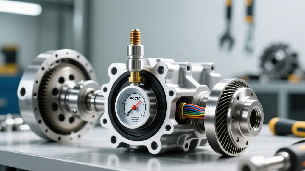
The Transmission Range Sensor (TRS), also known as the PRNDL switch or neutral safety switch, communicates the manual lever's physical position to the Transmission Control Module (TCM). If the internal wiper board wears out or moisture infiltrates the connector, the TCM receives conflicting gear signals. According to diagnostic databases like OBD-Codes, a P0705 (Transmission Range Sensor Circuit Malfunction) or P0706 code will force the TCM into a fail-safe mode, inhibiting shift solenoid operation entirely to prevent catastrophic gear binding.
How to differentiate the two:
- Shift Solenoid Faults: Usually trigger specific circuit or performance codes (e.g., P0751 Shift Solenoid A Performance, P0753 Electrical). The PRNDL display on the dash will accurately reflect the shifter position, but the transmission will slip, flare, or fail to upshift.
- Transmission Range Sensor Symptoms: The dash PRNDL display may flash, go blank, or show the wrong gear (e.g., shifter is in 'D', dash shows 'N'). You may experience a no-crank condition because the TCM/PCM does not recognize the Park or Neutral safety circuit. Line pressure may default to maximum, causing harsh, bone-jarring engagements.
Once you have verified via a bidirectional OBD2 scanner that the TCM is accurately reading the TRS input, you can confidently proceed to the shift solenoid replacement procedure outlined below.
Essential Tools and Safety Protocols
Replacing internal transmission solenoids requires precision and cleanliness. A single piece of lint or a stray metal shaving can jam a valve body spool valve. Gather the following equipment before beginning:
- Drainage & Lifting: Low-profile transmission jack, heavy-duty jack stands, and a high-capacity fluid catch pan (minimum 10-quart capacity for deep-pan applications).
- Precision Measurement: A calibrated 1/4-inch drive inch-pound torque wrench (crucial for valve body and pan bolts) and a digital multimeter (DMM) capable of measuring resistance down to 0.1 ohms.
- Fluids & Consumables: OEM-specified fluid (e.g., ACDelco Dexron VI for GM, ZF Lifeguard 8 for Chrysler/BMW 8HP units), new pan gasket or RTV sealant, and lint-free shop towels.
- Safety: Nitrile gloves and safety glasses. Transmission fluid is a known irritant and can be dangerously hot if the vehicle was recently driven.
Step-by-Step Shift Solenoid Replacement Guide
This guide focuses on the widely serviced GM 4L60E and 6L80 platforms, though the fundamental principles apply to most pan-accessible solenoids. For units like the ZF 8HP where solenoids are integrated into the Mechatronic unit, specialized sleeve and adapter replacement protocols apply, which we will note in the specifications table.
Phase 1: Pan Removal and Fluid Drain
- Temperature Check: Verify the transmission fluid temperature. For an accurate level check later, the fluid should be between 86°F and 122°F (30°C - 50°C) when checking the dipstick or leveling plug.
- Loosen the Pan: Break loose all pan bolts. Remove all but the four corner bolts. Loosen the front corner bolts slightly, then slowly loosen the rear corner bolts to tilt the pan, allowing the fluid to drain in a controlled stream into your catch pan.
- Filter Extraction: Once drained, remove the remaining bolts and lower the pan. Pull the transmission filter straight down. Note the O-ring seal left in the valve body bore; this must be extracted carefully using a plastic pick to avoid scoring the aluminum bore.
Phase 2: Electrical Testing & Solenoid Extraction
Never replace a solenoid without verifying the wiring harness first. According to technical bulletins from Sonnax, up to 30% of 'failed' solenoids are actually victims of chafed internal wiring harnesses or corroded case connectors.
- Resistance Testing: Set your DMM to Ohms. Probe the solenoid pins at the transmission case connector.
- On/Off Solenoids (e.g., 4L60E Shift Solenoid A/B): Expect 12 to 25 ohms at room temperature.
- PWM (Pulse Width Modulated) Solenoids (e.g., 6L80 3-5-R Clutch Solenoid): Expect much lower resistance, typically 3 to 10 ohms.
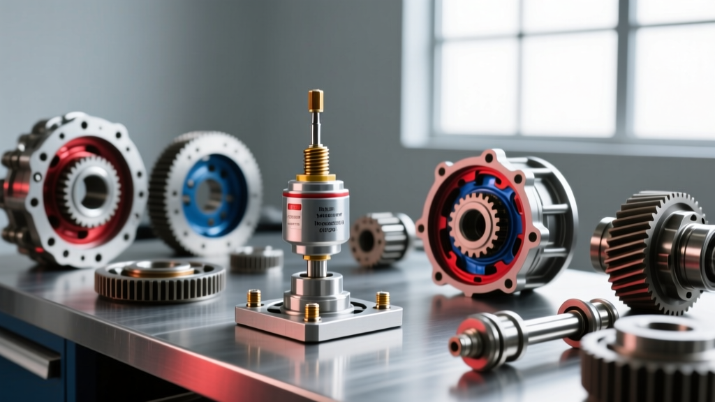
- Extraction: Locate the faulty solenoid on the valve body. Most are held in place by a metal retaining clip or a bolt-on bracket. Use needle-nose pliers to carefully remove the retaining clip. Twist the solenoid gently while pulling straight out to break the seal of the lower O-ring.
Phase 3: Installation and Torque Specifications
- Prep the New Solenoid: Lubricate the O-rings of the new solenoid with fresh transmission fluid. Never use petroleum jelly or assembly grease, as these can dissolve and clog the micro-valves in the valve body.
- Seating: Push the solenoid straight into the bore until it clicks or seats fully against the spacer plate. Reinstall the retaining clip, ensuring it is fully seated in its groove.
- Filter and Pan: Install the new filter, ensuring the O-ring is fully seated. Clean the pan with brake cleaner and a lint-free cloth. Install the new gasket.
- Torque Sequence: Hand-start all pan bolts. Using your inch-pound torque wrench, torque the pan bolts in a crisscross pattern. For the 4L60E, the spec is exactly 108 in-lbs (9 ft-lbs). For the 6L80, it is 12 Nm (106 in-lbs). Overtightening will warp the pan flange and cause permanent leaks.
2026 Cost Breakdown and Part Number Reference
Understanding the financial and technical scope of your repair is vital. The table below outlines real-world aftermarket and OEM pricing, alongside critical torque specifications for common transmission models.
| Transmission Model | Component / Part Number | Avg. Part Cost (2026) | Resistance Spec | Torque Spec (Mounting) |
|---|---|---|---|---|
| GM 4L60E / 4L65E | Shift Solenoid A/B (ACDelco 214-1892) | $25 - $40 each | 12 - 25 Ohms | N/A (Retaining Clip) |
| GM 6L80 / 6L90 | TEHCM Solenoid Body (ACDelco 24258479) | $180 - $260 | 3 - 10 Ohms (PWM) | 97 in-lbs (Valve Body) |
| Ford 6R80 | Solenoid Strategy / Mechatronic Kit | $350 - $500 | 2 - 6 Ohms | 8 Nm (71 in-lbs) |
| ZF 8HP (8HP45/70) | Mechatronic Sleeve / Adapter (Sonnax 95000K) | $45 - $75 | N/A (Mechanical Seal) | 10 Nm (Adapter Bolts) |
Post-Replacement Adaptation and Relearn Procedures
In the era of cable-driven throttle bodies, replacing a solenoid was a purely mechanical fix. Today, the TCM continuously monitors clutch volume and shift times, adapting solenoid duty cycles to compensate for clutch pack wear. If you replace a shift solenoid or the entire TEHCM (Transmission Electro-Hydraulic Control Module) without performing a relearn, the transmission will shift harshly or flare aggressively.
The Fast Adaptation Protocol
- Scan Tool Reset: Connect a bidirectional scanner capable of accessing the TCM. Navigate to 'Special Functions' and select 'Reset Transmission Adaptive Pressure' or 'Clear Shift Counts'.
- The Drive Cycle: Start the vehicle and allow it to idle in Park for 2 minutes, then shift to Reverse and Drive, holding each for 10 seconds while firmly applied on the brake pedal.
- On-Road Learning: Drive the vehicle on a flat, straight road. Perform 15-20 light-throttle upshifts (15% TPS) and 10 medium-throttle upshifts (30% TPS) from a complete stop through top gear. Allow the vehicle to coast down through the gears to trigger downshift adaptations.
Expert Warning: If you have ruled out transmission range sensor symptoms and successfully replaced the shift solenoids, but the vehicle still defaults to limp mode, verify the case-to-harness electrical connector. On high-mileage GM and Ford units, the plastic retaining tabs on the pass-through connector break, allowing the pins to back out under thermal expansion, causing intermittent open circuits that mimic a bad solenoid.