Introduction to Electronic Locker Rebuilds
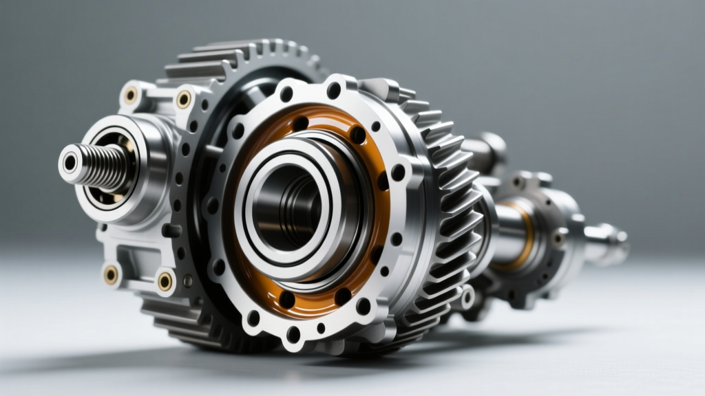
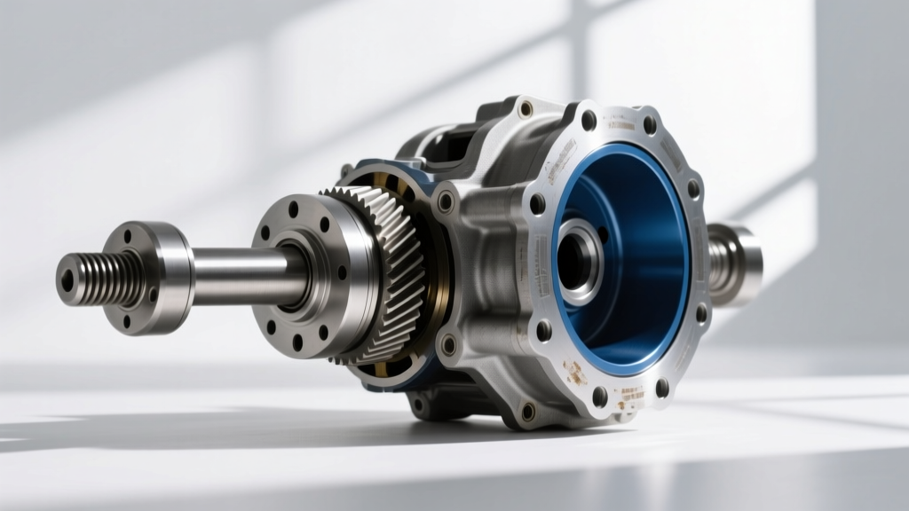
Rebuilding a traditional open or limited-slip differential requires precision, but when your axle is equipped with an electronic rear differential lock (often referred to as an eLocker or e-Diff), the complexity multiplies. You are no longer just setting ring and pinion gear patterns; you are rebuilding a motorized shift mechanism that demands exact clearances to engage the locking collar. Whether you are servicing a factory Toyota 8-inch e-Locker, a modern ZF electronic rear axle differential, or retrofitting an Eaton eLocker into a Dana 44 or GM 10-bolt, the fundamental rebuild procedures remain rooted in exact tolerances.
In this comprehensive 2026 step-by-step guide, we break down the complete differential rebuild procedure for an electronic locking carrier. We cover teardown diagnostics, ring and pinion setup, shift fork tolerances, and final actuator bench-testing to ensure your axle locks on command.
Phase 1: Teardown and Electronic Actuator Diagnostics
Before pressing out a single bearing, you must verify the health of the electronic components. The most common reason an electronic rear differential lock fails to engage is not internal gear damage, but rather a failed actuator motor or a chafed wiring harness.
- Drain and Extract: Drain the existing 75W-90 or 75W-140 GL-5 gear oil. Remove the axle shafts to expose the carrier. Unbolt the carrier bearing caps (mark them for reinstallation) and pry the carrier assembly out of the housing.
- Actuator Resistance Test: Disconnect the wiring harness from the differential housing. Using a digital multimeter, probe the actuator motor pins. A healthy 12V DC actuator motor should read between 2.5 and 4.0 ohms. If the multimeter reads infinite (an open circuit), the internal motor windings are burnt out, and the actuator must be replaced.
- Harness Inspection: Trace the wiring harness along the axle tube. In 60% of off-road applications, the harness rubs against the suspension link mounts or brake backing plates, causing a short circuit that blows the dashboard e-Locker relay.
Phase 2: Essential Tooling and Parts Matrix
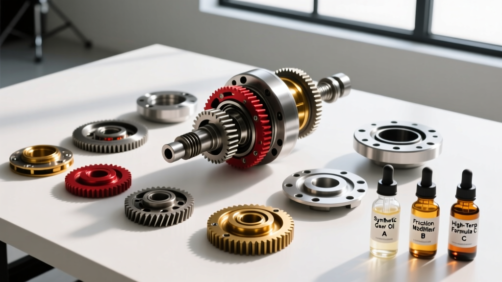
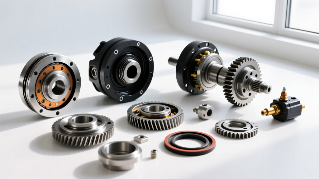
A successful rebuild requires specialized measuring tools and high-grade components. Do not reuse crush sleeves or carrier bearings. Below is the required parts and tooling matrix for a standard electronic locker rebuild.
| Component / Tool | Specification / Part Example | Est. Cost (2026) |
|---|---|---|
| Carrier & Pinion Bearings | Timken Set 10 (or OEM equivalent) | $85 - $120 |
| Crush Sleeve Eliminator Kit | Ratech 1000 Series (Model specific) | $35 - $50 |
| Dial Indicator & Magnetic Base | 0.0001-inch resolution | $60 - $90 |
| Inch-Pound Torque Wrench | Beam-style, 0-50 in-lbs range | $45 - $70 |
| Threadlocker | Loctite 272 (Red, High Strength) | $15 - $20 |
| Shift Fork Pad Kit | OEM Nylon/Bronze replacement pads | $25 - $40 |
Phase 3: Ring and Pinion Setup Procedures
With the electronic locking mechanism temporarily set aside, focus on the foundation of the differential: the ring and pinion gear set. Improper setup here will result in catastrophic gear failure, regardless of how well the locker functions.
Setting Pinion Depth and Preload
Install the pinion gear into the housing using the inner bearing cone. Use a pinion depth setting tool to measure the distance from the axle housing centerline to the pinion face. Adjust the pinion depth shims behind the inner bearing race until you match the OEM specification (usually stamped on the pinion head, e.g., '+2' or '-1').
Next, install the outer pinion bearing and set the pinion bearing preload. If using a traditional crush sleeve, tighten the pinion nut incrementally while checking rotational torque. For new Timken bearings, your target pinion preload is 15 to 25 inch-pounds of rotational resistance. We highly recommend using a crush sleeve eliminator kit, which replaces the one-time-use crush sleeve with a precision spacer and shims, making future electronic rear differential lock services significantly easier.
Setting Backlash and Gear Pattern
Mount the ring gear to the electronic locker carrier. Apply a drop of Loctite 272 to the ring gear bolts and torque them to 75 lb-ft in a star pattern. Install the carrier into the housing with the bearing caps matched to their original orientation.
Mount your dial indicator to the housing, with the plunger resting perpendicular to a ring gear tooth. Measure the backlash by rocking the ring gear back and forth while holding the pinion stationary. The target backlash for most street and light-trail applications is 0.007 to 0.009 inches. Adjust the carrier side shims or threaded adjusters to achieve this spec. Finally, apply yellow gear marking compound to three teeth on the ring gear, rotate the assembly under load, and verify the contact pattern. The pattern should be centered on the tooth face, slightly biased toward the heel under drive load.
Phase 4: Rebuilding the Electronic Locking Mechanism
This is the most critical phase specific to the electronic rear differential lock. The locking mechanism relies on a shift collar that slides laterally to mesh dog teeth with the internal side gear, effectively locking both axle shafts together.
Inspecting the Shift Fork and Collar
Remove the shift fork from the carrier. Inspect the nylon or bronze wear pads located at the tips of the fork that ride inside the shift collar groove. In high-mileage or heavily used lockers, these pads wear down. Measure the pad thickness with calipers; if the thickness is under 0.120 inches, the shift fork will not push the collar far enough to fully engage the dog teeth, resulting in a grinding noise or a failure to lock. Press in new OEM replacement pads.
Inspect the dog teeth on both the shift collar and the internal side gear. If the leading edges of the teeth are rounded off or 'shark-finned', the locker will pop out of engagement under heavy torque. Replace the collar and side gear as a matched set.
Actuator Integration
Reinstall the shift fork and collar onto the carrier. Before bolting the electronic actuator motor to the housing, manually push the shift fork to the 'locked' position. Verify that the collar fully bottoms out against the side gear hub. Apply a light coat of high-temp assembly lube to the shift collar groove, but keep all greases away from the electronic actuator contacts and limit switches.
Expert Diagnostic Tip: Never rely solely on the dashboard indicator light to confirm locker engagement during a rebuild. The dash light is often triggered by a simple position switch, not a load-bearing confirmation. You must visually verify full collar engagement through the axle shaft access hole before sealing the axle.
Phase 5: Final Assembly, Wiring, and Fluid Fill
With the carrier and gear set fully assembled, it is time to seal the unit and integrate the electronics.
- Bench Test the Actuator: Before installing the axle shafts, apply 12V directly to the actuator motor pins using a fused jumper wire. You should hear the internal DC motor whir, followed by a distinct, metallic 'clunk' as the shift fork moves the collar into the locked position. Reverse polarity to disengage. If the motor runs but the collar does not move, the internal actuator gear is stripped.
- Seal the Housing: Install the actuator O-ring (always use a new one, lubricated with gear oil to prevent pinching). Torque the actuator mounting bolts to 18 lb-ft.
- Routing the Harness: Route the wiring harness away from the exhaust and suspension linkages. Use high-temp split loom and adhesive-lined heat shrink to seal any splices. Secure the harness with rubber-cushioned P-clamps every 8 inches.
- Fluid Selection and Fill: Reinstall the axle shafts and the differential cover. Fill the housing with the manufacturer-specified gear oil. Most electronic lockers require 2.5 to 3.2 quarts of 75W-90 or 75W-140 Synthetic GL-5. Crucial Note: Do NOT add limited-slip friction modifiers to an electronic locking differential unless explicitly stated by the OEM. Friction modifiers can cause the dog clutches to slip rather than snap firmly into engagement, leading to premature wear of the shift collar.
Conclusion
Rebuilding an axle equipped with an electronic rear differential lock bridges the gap between heavy-duty mechanical wrenching and precise electrical diagnostics. By strictly adhering to pinion preload specs, verifying shift fork pad clearances, and bench-testing the actuator motor before final assembly, you ensure that your differential will deliver reliable, on-demand traction for years to come. For further technical specifications on aftermarket electronic locker integrations, consult resources like Eaton Automotive Differentials or drivetrain specialists such as Randy's Ring & Pinion. Proper maintenance, including regular 75W-90 fluid changes every 30,000 miles, remains the best defense against costly carrier replacements.