The Critical Role of the Input Speed Sensor in Nissan CVTs
Nissan’s Continuously Variable Transmissions (CVTs), primarily the Jatco-built JF011E (RE0F10A) and the newer JF016E (RE0F10D), represent a masterclass in hydraulic and electronic synergy. Unlike traditional stepped automatics like the GM 6L80 or ZF 8HP, which rely on fixed gear ratios and shift solenoids, a CVT requires real-time, micro-second adjustments to the primary and secondary pulley diameters. The linchpin of this operation is the transmission input speed sensor, often referred to as the primary speed sensor. As of 2026, the aftermarket and diagnostic landscape for these sensors has matured significantly, offering technicians and DIYers more reliable replacement options than ever before. However, understanding the exact Nissan CVT transmission speed sensor location and the nuances between OEM and aftermarket parts is crucial for a lasting repair.
Pinpointing the Nissan CVT Transmission Speed Sensor Location
One of the most common questions we receive at AutoGearNexus revolves around the physical placement of these sensors. If you are searching for the Nissan CVT transmission speed sensor location expecting to find it mounted externally on the transmission case—similar to the input/output sensors on a Ford 6R80 or a Chrysler 8HP—you will be disappointed.
On both the JF011E and JF016E platforms, the input (primary) and output (secondary) speed sensors are located internally. To access the input speed sensor, you must perform the following teardown sequence:
- Drain the CVT Fluid: Note that JF011E requires Nissan NS-2 fluid, while the JF016E requires the lower-viscosity NS-3. Never mix these.
- Remove the Transmission Pan: The pan is sealed with RTV silicone or a specialized gasket, depending on the exact model year and casing revision.
- Drop the Valve Body Strainer: Once the pan is off, the fluid strainer must be unbolted to expose the upper valve body casting.
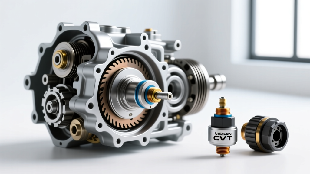
- Locate the Sensor: The input speed sensor is bolted directly to the valve body assembly, positioned precisely to read the magnetic reluctor ring (tone ring) attached to the primary pulley shaft.
Because the sensor operates in a hot, high-pressure environment bathed in CVT fluid, the wiring harness and sensor housing are subjected to extreme thermal cycling. The internal routing of the sensor harness connects to the main transmission case connector, which is a known failure point for fluid intrusion (wicking) on early 2007-2012 models.
2026 Buyer’s Guide: OEM vs. Aftermarket Input Sensors
When the TCM (Transmission Control Module) detects an erratic signal, it will throw a code and often trigger limp mode. When it is time to buy a replacement, the market offers several tiers of quality. Below is our 2026 comparison chart for Nissan CVT primary speed sensors.
| Brand / Tier | Part Number Example | Avg. Price (2026) | Warranty | Expert Verdict |
|---|---|---|---|---|
| Nissan Genuine (Hitachi) | 31935-1XF0C | $135 - $170 | 12 Months | The gold standard. Hitachi is the OEM manufacturer. Flawless signal waveform and exact-fit O-rings. |
| Standard Motor Products (SMP) | S10145 (Interchange) | $75 - $95 | 3 Years / 36k | Excellent aftermarket alternative. SMP's T-Series uses premium hall-effect chips that closely match OEM output. |
| Dorman / Economy Tier | Various | $40 - $60 | Limited Lifetime | Avoid for internal CVT applications. Inconsistent reluctor gap tolerances can cause micro-stutters at highway speeds. |
Buyer's Advice: Because the Nissan CVT transmission speed sensor location requires dropping the pan and potentially the valve body, the labor intensity of the job far outweighs the cost of the part. We strongly recommend purchasing the Nissan Genuine (Hitachi) sensor or a premium SMP unit. The $50 you save on an economy sensor is not worth the risk of dropping the pan a second time due to a faulty internal Hall-effect chip.
Advanced Diagnostics: P0715 and Oscilloscope Testing
Before ordering parts, proper diagnosis is mandatory. A failing input speed sensor typically triggers DTC P0715 (Input/Turbine Speed Sensor Circuit) or P1715 (Nissan-specific Input Speed Sensor code).
While a standard OBD2 scanner will read the code, professional diagnostics require an oscilloscope. According to JATCO Global technical documentation, the sensor is typically a 3-wire Hall-effect device:
- Pin 1: 5V Reference (from TCM)
- Pin 2: Signal Return (Square Wave)
- Pin 3: Ground
Hook your oscilloscope up to the signal wire while the vehicle is on a lift with the wheels spinning. You should see a clean, crisp 0V to 5V square wave. If the waveform shows rounded edges, voltage dropouts, or a skewed duty cycle, the sensor's internal magnet or the wiring harness is compromised. Furthermore, inspect the primary pulley reluctor ring for metallic debris. The CVT's internal magnets often attract fine clutch material, which can bridge the gap between the sensor and the tone ring, causing signal scattering.
Step-by-Step Replacement Protocol & Torque Specifications
Replacing the sensor requires meticulous attention to cleanliness and torque. The valve body of a Nissan CVT is highly sensitive to warping and cross-threading. Below are the critical factory specifications for the JF011E / JF016E platforms:
Fluid and Filtration
Always replace the transmission pan gasket and the internal strainer filter when performing this job. If your model uses a reusable RTV seal, ensure all old silicone is scraped off and cleaned with brake cleaner before applying a 2mm bead of high-temp automotive RTV. Allow it to cure per the manufacturer's instructions before refilling.
Factory Torque Specs
Using a calibrated inch-pound torque wrench is non-negotiable. Overtightening the valve body can distort the hydraulic channels, leading to delayed engagements and premature belt slip.
- Transmission Pan Bolts (10mm head): 7.9 Nm (69 in-lbs)
- Fluid Strainer Bolts: 8.8 Nm (78 in-lbs)
- Speed Sensor Mounting Bolt: 6.5 Nm (57 in-lbs)
- Valve Body to Case Bolts (if removed): 8.8 Nm (78 in-lbs) in a crisscross pattern
The O-Ring Rule
The input speed sensor relies on a small Viton O-ring to seal the electrical connector from pressurized CVT fluid. Never reuse the old O-ring. Lubricate the new O-ring with a drop of fresh NS-2 or NS-3 fluid before seating it into the valve body harness plug. A dry O-ring will pinch and tear upon insertion, leading to fluid intrusion into the electrical connector, which will inevitably cause a short circuit and destroy the TCM driver circuit.
Post-Replacement Calibration and TCM Resets
Once the new sensor is installed and the transmission is refilled with the correct volume of fluid (typically 4.5 to 5.5 liters for a dry fill, less for a pan-drop), the job is not entirely finished. Modern Nissan TCMs adapt to the slight signal variations of aging sensors. When installing a new input speed sensor, it is highly recommended to use a bi-directional scan tool to perform a TCM Memory Clear and reset the CVT fluid deterioration data.
As detailed in the NICOclub Nissan Technical Archives, failing to reset the TCM adaptation values can result in harsh initial engagements or a 'rubber-band' throttle feel as the computer attempts to reconcile the new, crisp sensor data with old, degraded hydraulic pressure maps. Take the vehicle for a 15-minute drive cycle, allowing the CVT to cycle through its full ratio spread at varying throttle positions to relearn the primary pulley speed parameters.
Final Thoughts
Mastering the Nissan CVT transmission speed sensor location and replacement procedure is a rite of passage for modern transmission technicians and advanced DIYers. By investing in OEM-grade Hitachi components, utilizing an oscilloscope for definitive diagnostics, and adhering strictly to factory torque specifications, you can restore the seamless, invisible shifting that Nissan's CVTs were designed to deliver. For more deep-dives into transmission electronics, sensor waveforms, and drivetrain diagnostics, continue exploring the AutoGearNexus knowledge base.