The Electromechanical Root of PTO Clutch Burning Smells
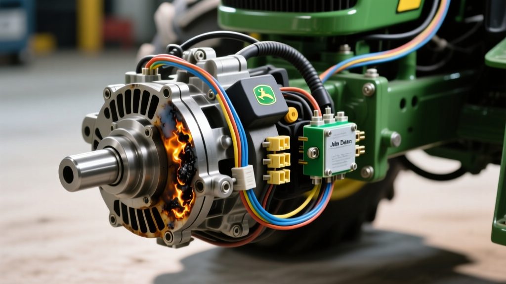
When a driver experiences a burning smell in a traditional automotive manual transmission—such as those paired with a Tremec TR-6060 or a ZF 6-speed—the culprit is usually a slipping organic or Kevlar friction disc overheating due to rider error or a failing hydraulic throw-out bearing. However, in the agricultural and commercial landscaping sectors, a burning clutch smell originating from a lawn or utility tractor points to an entirely different failure mode. In machines equipped with an electromagnetic Power Take-Off (PTO), the burning odor of melting epoxy, hot copper, and scorched friction material is rarely just a mechanical issue; it is almost always an electrical fault disguised as mechanical wear.
Unlike automotive hydraulic clutch systems that rely on fluid pressure, electric PTO clutches (commonly manufactured by Warner Electric or Ogura for John Deere) rely entirely on electromagnetic clamping force. This clamping force is directly proportional to the voltage and current supplied to the coil. If the electrical circuit suffers from a voltage drop, the clutch partially engages. This micro-slipping generates immense friction—easily exceeding 400°F at the rotor-stator interface—which rapidly degrades the friction surfaces, boils the internal epoxy potting, and produces a distinct, acrid burning smell. To accurately diagnose this, a technician must move beyond the mechanical air gap and consult a john deere electric pto clutch wiring diagram to trace the 12-volt supply circuit, safety interlocks, and grounding paths.
Decoding the John Deere Electric PTO Clutch Wiring Diagram
Modern John Deere tractors, ranging from the 100-series lawn tractors to the heavier X300 and X500 series, utilize complex wiring harnesses that route 12V power through multiple safety interlock switches before it ever reaches the PTO clutch coil. When diagnosing a burning smell, the wiring diagram is your primary diagnostic map. The circuit typically follows this path:
- Power Source: 12V from the battery through a main 30A or 40A fuse.
- Ignition & PTO Switch: Power flows through the ignition switch to the dashboard PTO engagement switch.
- Safety Interlocks: The circuit passes through the seat switch (operator presence), brake pedal switch, and transmission neutral safety switch (especially on models with the K46 or K57 hydrostatic transmissions).
- PTO Relay: A heavy-duty 30A relay acts as the bridge, preventing high amp-draw from burning out the delicate dashboard PTO switch.
- The Clutch Coil: Finally, power reaches the 2-pin connector on the PTO clutch itself, completing the circuit through the chassis ground.
A common failure point revealed by the wiring diagram is the seat switch bypass or a corroded brake switch terminal. If an interlock switch is failing, it may allow 9 or 10 volts to pass instead of a full 12.4 volts. The clutch coil will energize enough to create a magnetic field, but not enough to fully lock the armature plate against the rotor. The resulting slip is what causes the burning smell. For comprehensive wiring schematics and diagnostic flowcharts, referencing community-driven technical archives like Green Tractor Talk or official John Deere Technical Information manuals is highly recommended.
Step-by-Step Voltage Drop & Resistance Diagnostics
Before replacing a $300 clutch assembly, you must verify whether the burning smell is the result of a failing component or a failing circuit. Grab a digital multimeter (DMM) and follow these precise diagnostic steps.
Step 1: Static Coil Resistance Testing
Disconnect the 2-pin wiring harness connector from the PTO clutch. Set your multimeter to measure Ohms (Ω). Place the probes on the two pins of the clutch coil (not the harness side). According to engineering specifications from Warner Electric technical documents, a healthy 12V PTO clutch coil should read between 2.5 and 4.0 ohms at room temperature (70°F).
Expert Insight: If your reading is above 10 ohms, the internal windings are degrading or suffering from a heat-induced micro-fracture. If the reading is below 1.0 ohm, the coil has an internal short. In either case, the coil is generating excessive heat internally, which bakes the epoxy and causes the burning smell. The clutch must be replaced.
Step 2: Dynamic Voltage Drop Under Load
If the coil resistance is nominal, the issue lies in the wiring harness. Reconnect the harness. Set your DMM to DC Volts. Back-probe the connector while the PTO is engaged and the engine is running at operational RPM (typically 3200-3600 RPM for full PTO speed).
- Healthy Circuit: You should read a minimum of 11.8V to 12.2V at the clutch connector.
- Failing Circuit: If you read 10.5V or lower, you have a severe voltage drop.
To isolate the drop, measure the voltage at the battery (should be 13.8V-14.4V with the alternator charging). Then, measure the voltage at the input side of the PTO relay, and the output side. A voltage drop of more than 0.5V across any single switch, relay, or wire segment indicates high resistance due to corrosion, loose crimps, or failing internal contacts. Clean the terminals with electrical contact cleaner and apply dielectric grease, or replace the faulty relay/switch.
Diagnostic Matrix: Smell Profiles vs. Electrical Faults
Not all burning smells are identical. The specific odor profile, combined with electrical readings, can pinpoint the exact failure mode without tearing down the PTO shaft.
| Odor Profile | Electrical Symptom | Root Cause | Corrective Action |
|---|---|---|---|
| Acrid, melting plastic / ozone | Coil reads > 10Ω or < 1Ω | Internal coil short/open; epoxy potting is melting due to internal arcing. | Replace PTO clutch assembly (Warner/Ogura unit). |
| Burning friction material / hot iron | Voltage at clutch is 9V - 11V | Voltage drop across safety interlocks or relay causing continuous micro-slip. | Trace wiring diagram; replace corroded relay or seat switch. |
| Hot metallic / scorched grease | Voltage is a perfect 12.4V+ | Mechanical air gap is too wide, or rotor bearing is seized. | Adjust air gap to 0.012' or replace worn clutch bearing. |
| Electrical smoke from harness | Blown 30A fuse or melted connector | Short to ground in the wiring harness near the steering column or deck. | Repair harness loom; replace melted pigtail connector. |
Mechanical Air Gap Adjustment & Torque Specifications
If your electrical diagnostics confirm a perfect 12.2V supply and a healthy 3.2Ω coil resistance, but the clutch is still slipping and burning, the issue is mechanical. Over time, the friction surfaces of the PTO clutch wear down, widening the air gap between the rotor and the armature. Electromagnetic force decreases exponentially as the air gap increases. If the gap exceeds 0.020 inches, the clutch will slip under the heavy load of a 60-inch mower deck, generating massive heat.
Consulting Ogura Clutch engineering data, the optimal air gap for most John Deere electric PTO clutches is between 0.010 and 0.015 inches. Using a feeler gauge, measure the gap between the rotor and armature at the three adjustment slots. Loosen the lock nuts and adjust the set screws evenly until the gap is precisely 0.012 inches all the way around.
When reinstalling the PTO clutch onto the engine crankshaft, proper torque is critical to prevent the clutch from wobbling, which destroys the internal bearing and causes friction heat. For standard John Deere vertical shaft engines (using a 5/8'-18 or 3/4'-16 threaded crank), apply a medium-strength threadlocker (such as Blue Loctite 243) to the threads and torque the PTO shaft nut to 55 to 65 lb-ft. Never use an impact wrench to tighten the PTO nut, as this can shatter the internal ceramic friction linings.
2026 Replacement Costs & Part Number Cross-References
If the coil is internally shorted or the friction surfaces are glazed beyond repair, replacement is mandatory. As of 2026, sourcing the correct unit requires matching the specific crankshaft diameter and wiring harness plug type.
- OEM John Deere Parts: Part numbers like AM132735 or MIA11668 typically retail between $280 and $360 through official dealerships.
- Aftermarket Equivalents: The exact same clutches, manufactured by Warner Electric (e.g., 5218-45) or Ogura (GT2.5-110), can be sourced through agricultural suppliers for $160 to $220.
Always verify the wiring diagram for your specific serial number break before ordering. John Deere frequently transitioned from spade-terminal connectors to waterproof molded 2-pin Deutsch-style connectors in the mid-2010s. Installing a clutch with the wrong pigtail will force you to splice wires, introducing a new point of resistance that will inevitably lead to another voltage drop, more micro-slipping, and the dreaded burning clutch smell all over again.