Understanding Transmission Burnout: Beyond the Burnt Smell
When drivers ask, how can you tell if you have transmission problems, the answer often lies in the severe degradation of internal friction materials—a condition technicians refer to as clutch burnout. In the automotive repair industry, 'transmission burnout procedures' do not refer to doing donuts in a parking lot; rather, they encompass the systematic diagnostic protocols used to confirm, measure, and address the thermal destruction of clutch packs, bands, and transmission fluid. As of 2026, with the widespread integration of 8-speed and 10-speed automatics like the ZF 8HP and Ford 10R80, detecting early-stage burnout requires moving past simple dipstick checks and utilizing advanced bi-directional scan tools and hydraulic pressure testing.
Clutch burnout occurs when the friction material on the steel and friction plates overheats, glazes, or completely disintegrates. This generates immense debris that contaminates the valve body, clogs the cooler, and destroys the torque converter. Below, we detail the expert-level procedures to diagnose a burnt transmission, complete with real-world specifications and repair frameworks.
Phase 1: Fluid Analysis and Olfactory Diagnostics
The first step in any burnout diagnostic procedure is evaluating the automatic transmission fluid (ATF). Modern synthetic fluids like Dexron VI, Mercon LV, and ZF Lifeguard 8 are engineered to resist thermal breakdown, meaning that if they smell burnt, the internal damage is already severe.
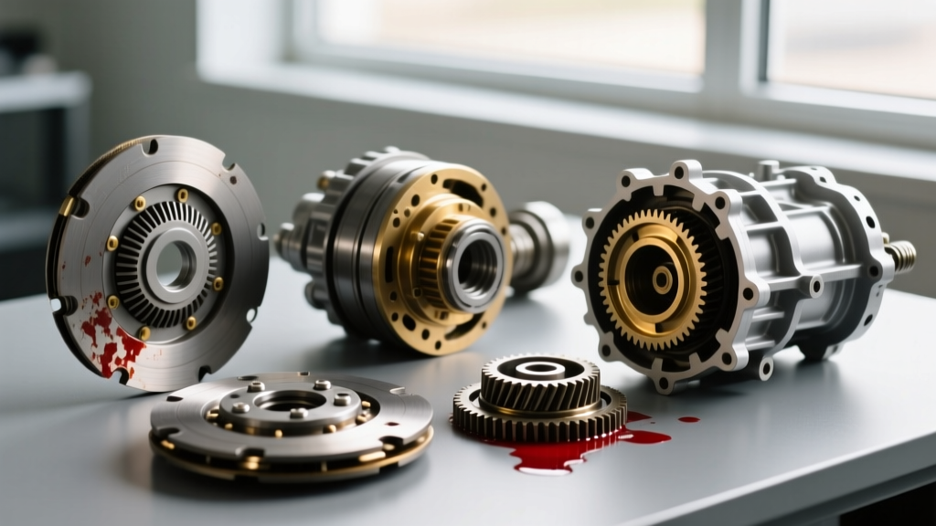
- Color and Viscosity: Healthy ATF is translucent red or light amber. Burnt fluid turns dark brown or opaque black. If you rub the fluid between your fingers and feel a gritty, metallic paste, the clutch facing material has physically separated from the friction plates.
- The Olfactory Test: A distinct 'burnt toast' odor indicates that the paper/cellulose-based friction linings have exceeded their thermal threshold (typically above 350°F / 176°C). An acrid, chemical smell points to severe fluid oxidation and varnishing of the valve body spool valves.
- Magnet Inspection: Drop the transmission pan. A light gray paste on the pan magnet is normal wear. Thick, black sludge with visible copper or brass flakes indicates that the bushings and thrust washters have failed alongside the clutches.
Phase 2: Electronic and Hydraulic Diagnostic Procedures
If the fluid shows signs of thermal degradation, the next step is to determine why the burnout occurred. Was it a mechanical failure, or a hydraulic control issue?
Scan Tool PID Analysis (Slip Rate Calculation)
Using a bi-directional scanner (such as an Autel MaxiSys or Snap-on Zeus), monitor the Turbine Speed Sensor (TSS) and Output Speed Sensor (OSS) PIDs while driving. In a locked-up gear (e.g., 4th gear in a GM 6L80, which is a 1:1 ratio), the TSS and OSS RPMs should be nearly identical. If the TSS reads 2,800 RPM while the OSS reads 2,100 RPM under load, you have a 25% slip rate. This mathematically confirms that a specific clutch pack (in this case, the 3-5-R clutch) is burned out and slipping.
Line Pressure Testing
Low hydraulic pressure is the leading cause of clutch burnout. Connect a 0-300 PSI mechanical gauge to the transmission line pressure tap.
- GM 6L80 / 6L90: Base line pressure should sit around 55-70 PSI at idle in Drive. Under heavy throttle or when commanded via the scan tool, pressure should spike to 220-250 PSI. If pressure maxes out at 120 PSI, the pressure regulator valve in the oil pump is likely worn. Installing a Sonnax pressure regulator valve kit (e.g., part number 77901-04K) is a mandatory best practice during the rebuild.
- ZF 8HP45 / 8HP70: These units utilize a variable displacement vane pump. Low pressure here is frequently caused by the notorious ZF mechatronic sleeve leaks or cracked adapter bushings, leading to the 'Trans Failsafe Prog' warning and subsequent E-clutch or A-clutch burnout.
Stall Speed Testing
With the vehicle secured, brakes fully applied, and the engine at operating temperature, apply wide-open throttle (WOT) for no more than 3 seconds. A normal stall speed for a Ford 6R80 is roughly 2,000-2,400 RPM. If the engine RPM flares to 3,500+ RPM, the forward clutch pack or one-way clutch has completely burned out and is no longer holding the stator or input shaft.
Phase 3: Teardown and Air-Testing Procedures
Once internal burnout is confirmed, the transmission must be removed and torn down. The 'air test' is the definitive procedure to pinpoint the exact failure point before disassembling the clutch drums.
With the valve body removed and the transmission case mounted on a bench, apply 30-40 PSI of regulated shop air directly into the clutch apply feed holes in the case or drum.
- The 'Thud' Test: You should hear a distinct, solid 'thud' as the piston compresses the clutch pack and return spring.
- Leak-Down Test: Hold the air pressure for 15 seconds. If you hear hissing from the drum seals or the piston O-rings, the hydraulic seal has failed. This lack of clamping force caused the friction plates to slip, generating the heat that burned the clutches.
- Wave Plate Inspection: In GM 6L80 units, the 3-5-R wave plate is notorious for fracturing. A broken wave plate drops into the clutch pack, acting like a cheese grater and instantly burning out the friction material. Always inspect the wave plate for stress fractures during teardown.
Burnout Severity Matrix and Repair Actions
| Burnout Stage | Fluid Condition & Symptoms | Diagnostic Confirmation | Required Repair Procedure |
|---|---|---|---|
| Stage 1: Mild Glazing | Dark red fluid, slight odor. Minor shudder on 3-4 shift. | Scan tool shows 2-5% slip under heavy load. | Fluid exchange, cooler flush, reprogram TCM adaptive tables. |
| Stage 2: Moderate Burn | Brown fluid, burnt smell. Slipping in specific gears (e.g., Reverse). | Line pressure drops under load; Air test reveals piston seal leak. | Pan drop, replace specific burnt clutch pack, install Sonnax valve body updates, new torque converter. |
| Stage 3: Catastrophic | Black, opaque fluid with metallic debris. Vehicle immobile or RPM flares wildly. | Stall test failure; TSS/OSS RPM mismatch across multiple gears. | Full teardown, Raybestos GPZ master rebuild kit, new pump, machine shop case machining, custom stall converter. |
Rebuild Best Practices and 2026 Cost Implications
When addressing severe clutch burnout, simply swapping the friction plates is a recipe for a comeback. The debris from burnt clutches embeds itself into the torque converter and the porous friction material of the bands.
Component Replacement Best Practices:
- Friction Materials: Upgrade to high-energy friction materials. For high-torque applications or heavy towing, technicians rely on Raybestos Powertrain GPZ clutch kits, which utilize a specialized friction paper designed to withstand higher thermal loads without glazing.
- Torque Converter: A burnt transmission requires a new or professionally remanufactured torque converter. Attempting to flush a converter full of burnt clutch cellulose is impossible; the debris will eventually dislodge and destroy the new transmission.
- Cooler Flushing: Use a dedicated hot-flush machine with a pulsating flow to clear the transmission cooler lines. If the cooler is clogged with burnt debris, bypass it and install a new auxiliary transmission cooler.
Financial Framework (2026 Estimates):
Addressing a Stage 3 burnout is a major financial undertaking. A master rebuild kit (frictions, steels, seals, bushings) ranges from $450 to $850 depending on the transmission model. A remanufactured torque converter adds $350 to $700. When factoring in machine shop services (case boring, valve body reaming) and 12-18 hours of skilled labor, consumers should expect total repair invoices between $3,200 and $5,500 for late-model 8-speed and 10-speed automatics. For deeper industry insights and case studies on transmission failure modes, Transmission Digest remains an invaluable resource for both technicians and informed vehicle owners.
Summary
Knowing how can you tell if you have transmission problems related to burnout requires a multi-sensory and data-driven approach. By combining fluid analysis, bi-directional slip rate calculations, hydraulic pressure testing, and meticulous air-testing procedures, you can accurately diagnose the root cause of friction material failure. Addressing the underlying hydraulic or mechanical defect—not just replacing the burnt clutches—is the only way to ensure long-term drivetrain reliability.