The Blame Game: TCM Failure vs. Speed Sensor Faults
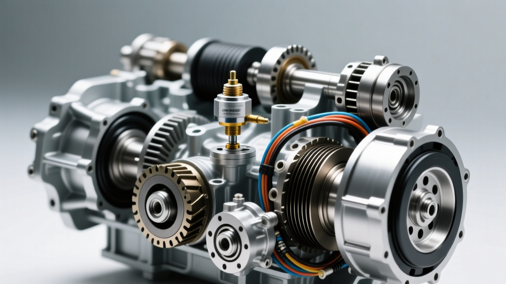
When a modern vehicle enters limp mode, exhibits erratic shift points, or triggers a P0700-series diagnostic trouble code (DTC), the immediate suspect is often the automatic transmission speed sensor. However, as transmission architectures have evolved, the line between a failed sensor and a failing Transmission Control Module (TCM) has blurred. In 2026, with the proliferation of integrated mechatronic units and internal electro-hydraulic control modules, misdiagnosing a TCM fault as a simple sensor failure is one of the most costly mistakes a technician or DIYer can make.
The automatic transmission speed sensor—whether acting as the Input Speed Sensor (ISS) or Output Speed Sensor (OSS)—provides the foundational RPM data the TCM uses to calculate slip, command line pressure, and time shift solenoids. If the TCM's internal circuit board suffers from micro-fractures, thermal degradation, or moisture ingress, it will fail to read a perfectly healthy sensor's signal. The result? The scan tool points to a sensor circuit code, but the root cause lies deep inside the TCM.
Decoding the OBD-II Trail: P0700, P0715, and P0720
Before tearing into the transmission pan, you must understand how the OBD-II network reports these faults. The TCM monitors the frequency and voltage of the speed sensor signals. When the signal drops out or becomes implausible compared to wheel speed data, a code is set.
| OBD-II Code | Description | Primary Suspect | Secondary Suspect (The TCM Factor) |
|---|---|---|---|
| P0700 | Transmission Control System (MIL Request) | Gateway / CAN Bus Issue | Internal TCM processor failure or loss of 5V reference bus. |
| P0715 | Input/Turbine Speed Sensor 'A' Circuit | ISS wiring, connector, or sensor magnet. | TEHCM internal solder joint crack (common on GM 6L80/6L90). |
| P0717 | Input/Turbine Speed Sensor 'A' Circuit No Signal | Dead Hall-effect sensor or severed harness. | TCM internal pull-up resistor failure. |
| P0720 | Output Speed Sensor Circuit | OSS debris accumulation or sensor failure. | Mechatronic unit internal trace corrosion (ZF 8HP). |
| P0722 | Output Speed Sensor Circuit No Signal | Broken OSS mounting tab or air gap issue. | TCM signal processing ASIC chip thermal failure. |
Source reference: For comprehensive code definitions and manufacturer-specific variations, consult the OBD-Codes P0715 Reference database.
Architectural Differences: Where the TCM and Sensors Live
Diagnosing an automatic transmission speed sensor requires knowing exactly where the TCM resides, as this dictates your testing methodology and replacement costs.
GM 6L80 / 6L90: The TEHCM Paradigm
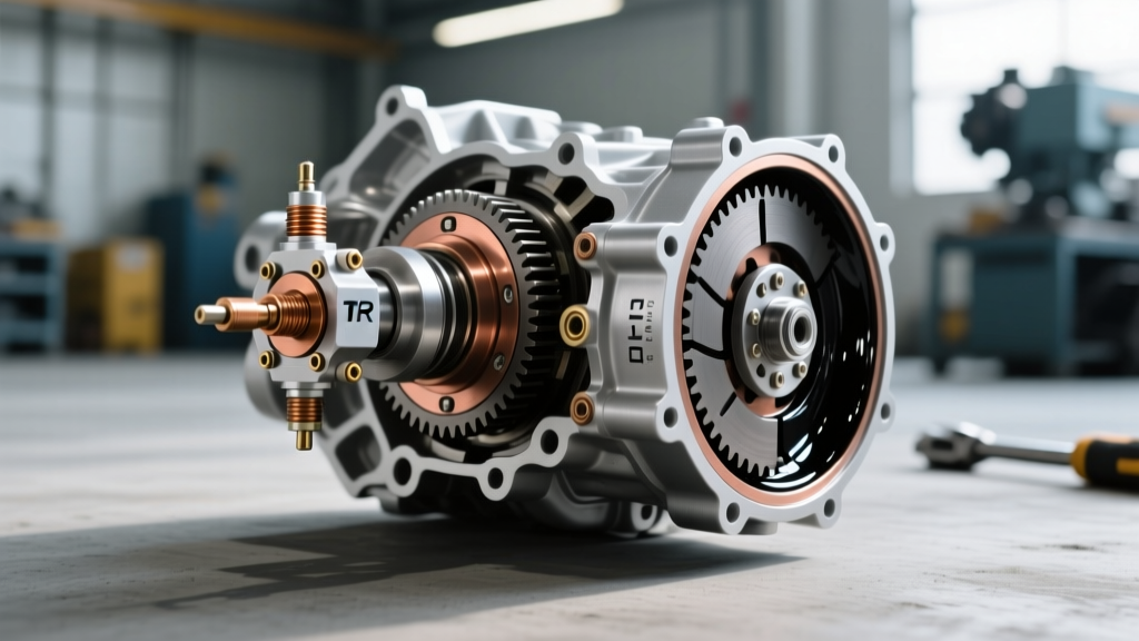
General Motors moved the TCM inside the transmission fluid pan on the 6L80 and 6L90 series, creating the Transmission Electro-Hydraulic Control Module (TEHCM). The ISS and OSS plug directly into the TEHCM harness. Because the TEHCM is subjected to constant thermal cycling and fluid vibration, the internal solder joints connecting the sensor pins to the TCM circuit board are notorious for cracking. A P0715 code here is just as likely to be a $600 TEHCM failure as it is a $40 sensor.
ZF 8HP: The Mechatronic Integration
In the ubiquitous ZF 8-speed (found in BMW, Audi, Chrysler, and Ford applications), the TCM is fully integrated into the Mechatronic unit (the valve body and solenoid assembly). The speed sensors are often embedded directly into the Mechatronic housing or mounted on a dedicated sensor board. You cannot simply unplug a speed sensor from the outside of the case; diagnosing a fault requires dropping the pan, removing the Mechatronic, and testing the internal ribbon cables and board traces.
Step-by-Step Diagnostic Framework: Isolating the Culprit
To separate a bad sensor from a bad TCM, you must move beyond basic code reading and perform dynamic electrical testing. Here is the definitive 2026 diagnostic protocol.
Phase 1: Scan Tool Data PID Monitoring & Graphing
Connect a bi-directional scan tool capable of graphing PIDs (Parameter Identification Data). Command the vehicle on a lift with the drive wheels spinning.
- Graph ISS vs. Engine RPM: In the torque converter lock-up phase, ISS and Engine RPM should be nearly identical. If the ISS PID drops to zero intermittently while Engine RPM remains steady, you have a circuit dropout.
- Graph ISS vs. OSS: The TCM calculates gear ratios by dividing ISS by OSS. If the scan tool shows a 'Gear Ratio Error' (e.g., P0731) alongside a speed sensor code, the TCM is seeing a signal, but it's erratic or noisy, pointing more toward sensor debris or internal TCM filtering failure rather than a dead circuit.
Phase 2: Electrical Bench Testing (Multimeter & Oscilloscope)
Modern automatic transmission speed sensors are predominantly Hall-effect (3-wire) or Magneto-Resistive, requiring a power supply, ground, and signal wire. Variable Reluctance (2-wire AC) sensors are largely obsolete in modern passenger automatics.
Expert Tip: Never pierce the wires with a test light or multimeter probe. Always back-probe the connector to avoid creating a path for capillary action, which will wick transmission fluid directly into the TCM over time.
The Oscilloscope Test:
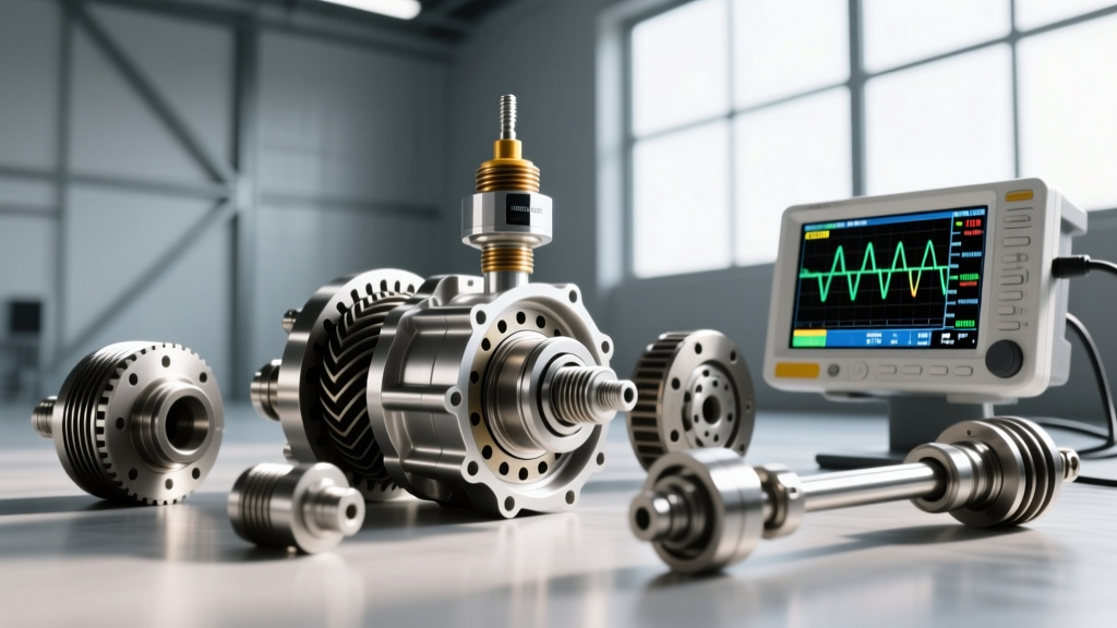
Back-probe the signal wire and set your scope to a 5V scale. Spin the output shaft by hand or use a drill on the input shaft. A healthy Hall-effect automatic transmission speed sensor will produce a crisp, clean 0-5V square wave. If the square wave shows rounded corners, voltage sag (e.g., dropping to 3.8V instead of 5V), or excessive noise on the baseline, the issue is usually wiring resistance or a failing sensor magnet. If the signal wire shows a perfect 5V reference but zero switching activity while the shaft spins, the sensor's internal Hall IC is dead. If the 5V reference is missing entirely at the sensor plug, the TCM's internal voltage regulator has failed.
Real-World Repair Costs and Part Numbers (2026 Market Data)
Understanding the financial risk of misdiagnosis is critical. Replacing a sensor when the TCM is at fault results in wasted labor, fluid, and parts. Below is a snapshot of current market pricing and OEM part data.
| Transmission Model | Component | OEM / Premium Part Number | Est. Part Cost (2026) | Labor & Programming Notes |
|---|---|---|---|---|
| GM 6L80 / 6L90 | Input Speed Sensor (ISS) | ACDelco 24232146 | $45 - $65 | Requires pan drop, 4-6 qts Dexron VI. No programming. |
| GM 6L80 / 6L90 | TEHCM (TCM + Solenoids) | ACDelco 24253225 (Varies by VIN) | $450 - $750 | Requires GM SPS programming and VCI module. High labor time. |
| ZF 8HP45 / 8HP70 | OSS / Sensor Board | ZF 1078.207.235 | $180 - $250 | Mechatronic must be partially disassembled. Clean room environment recommended. |
| ZF 8HP45 / 8HP70 | Full Mechatronic Unit (TCM) | ZF 1087.298.055 | $1,900 - $2,600 | Requires ZF-specific coding, adaptation resets, and 8-10 qts ZF Lifeguard 8. |
For in-depth teardown procedures and valve body diagnostics, technicians frequently rely on Sonnax Technical Resources for updated bulletins and repair sleeves.
Expert Torque Specs and Reinstallation Protocols
If your oscilloscope and multimeter tests confirm the automatic transmission speed sensor is indeed the culprit, proper reinstallation is paramount. An incorrect air gap between the sensor tip and the reluctor ring will cause a weak signal, triggering a P0717 or P0722 code the moment the vehicle reaches operating temperature and the metal expands.
Critical Torque Specifications
- GM 6L80 ISS/OSS Mounting Bolts (M6x1.0): 8 to 10 Nm (71 to 89 lb-in). Do not exceed 10 Nm, as the aluminum case threads strip easily.
- GM 6L80 TEHCM-to-Case Bolts (M6): 10 to 12 Nm (89 to 106 lb-in).
- ZF 8HP Mechatronic-to-Case Bolts (M6): 10 Nm (88 lb-in), tightened in a specific spiral sequence starting from the center to prevent valve body warping.
- Transmission Pan Bolts (GM/ZF): 8 to 10 Nm. Use a calibrated inch-pound torque wrench; standard foot-pound wrenches lack the resolution for these small fasteners.
The Air Gap and Debris Factor
Before installing the new sensor, inspect the reluctor ring. On the 6L80, the ISS reads off a stamped steel ring on the input shaft. If the transmission has experienced clutch pack wear, ferrous metallic debris will cling to the sensor's magnetic tip. Always install a new sensor with a clean, lint-free surface, and consider adding an inline magnetic transmission filter if the fluid showed high metallic content during the pan drop.
Final Synthesis: Trust the Waveform, Not Just the Code
The assumption that a speed sensor code automatically means a dead sensor is a relic of older, simpler vehicles. In modern platforms like the GM 6L80 and ZF 8HP, the TCM and the automatic transmission speed sensor are inextricably linked in a hostile thermal environment. By utilizing an oscilloscope to verify the 5V reference and the square wave signal integrity, you can definitively prove whether the fault lies in the $50 sensor or the $2,000 mechatronic brain. Diagnose the circuit, verify the waveform, and let the data dictate the repair.