The Engineering Definition of the Clutch Factor
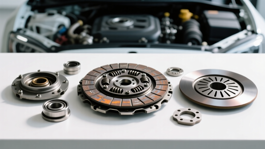
In automotive transmission diagnostics, the term 'clutch factor' is frequently misunderstood as a subjective feel or engagement characteristic. In reality, the clutch factor is a quantifiable engineering metric representing the reserve torque capacity of the clutch assembly relative to the engine's peak output. Mathematically, the torque capacity (Tc) of a clutch is defined by the equation: Tc = μ × F × Re × N. Here, μ represents the dynamic friction coefficient of the friction material, F is the clamping force exerted by the diaphragm spring, Re is the mean effective radius of the friction disc, and N is the number of friction surfaces.
As a vehicle accumulates mileage, the clutch factor degrades. This degradation is rarely linear; it is a complex interplay of friction material wear (reducing Re and altering μ), diaphragm spring fatigue (reducing F), and thermal cycling. For technicians and enthusiasts operating in 2026, understanding how this mathematical reserve diminishes is critical for accurately diagnosing clutch slip, chatter, and premature failure before catastrophic drivetrain damage occurs.
Quantifiable Wear Signs: Measuring Physical Degradation
Before a clutch completely fails to transmit torque, the physical dimensions of the assembly shift. Diagnosing these shifts requires precise measurement rather than guesswork.
Pedal Free-Play and Hydraulic Stroke
The earliest indicator of clutch factor loss due to friction material wear is a reduction in pedal free-play. As the friction disc thins, the diaphragm spring fingers extend further toward the release bearing. In hydraulic systems, this pushes the master cylinder pushrod deeper, reducing the physical free-play at the pedal pad.
- Hydraulic Systems: OEM specifications typically demand 0.50 to 1.00 inches of free-play. A measurement below 0.25 inches indicates the release bearing is riding on the diaphragm fingers, causing continuous slip, immense heat generation, and a rapid collapse of the clutch factor.
- Cable-Actuated Systems: Require 1.00 to 1.50 inches of free-play. Cable stretch combined with disc wear can mask the true wear state, necessitating inspection of the clutch fork travel at the bell housing.
Flywheel Step Height and Diaphragm Geometry
A critical, often overlooked variable in clutch factor retention is the flywheel step height. The step height dictates the installed position of the pressure plate relative to the diaphragm spring's optimal clamping geometry. If a flywheel is resurfaced improperly and the step is lost, the clamping force (F) drops exponentially, regardless of how new the friction disc is.
For example, General Motors LS-series V8 engines mandate a strict 0.030-inch step height on the flywheel. Ford Modular and Coyote V8 engines often require a 0.000-inch to 0.050-inch step depending on the specific clutch application. Deviating by even 0.015 inches can reduce the clutch factor by up to 20%, leading to immediate high-RPM slip.
Friction Material Science and Mu Retention
The friction coefficient (μ) is not a static number; it changes based on temperature, slip speed, and wear depth. According to testing protocols outlined by SAE International J2522 for clutch friction materials, different compounds exhibit vastly different degradation curves. Selecting the wrong material for a specific torque profile will accelerate the loss of the clutch factor.
| Friction Material | Dynamic μ (Avg) | Optimal Temp Range | Clutch Factor Retention Profile | Expected Lifespan (Street) |
|---|---|---|---|---|
| Organic (Kevlar-reinforced) | 0.27 - 0.33 | 150°F - 350°F | Gradual linear drop; smooth engagement | 60,000 - 90,000 miles |
| Cerametallic (Puck-style) | 0.38 - 0.45 | 300°F - 600°F | High retention under load; abrupt drop-off at extreme heat | 30,000 - 50,000 miles |
| Carbon/Carbon (Multi-plate) | 0.20 - 0.25 | 400°F - 1200°F | Requires heat to achieve peak μ; poor cold retention | Racing only (Cycle-based) |
| Sintered Iron | 0.40 - 0.50 | 200°F - 800°F | Extreme durability; harsh engagement damages drivetrain | 40,000 - 70,000 miles |
When diagnosing a slipping clutch, technicians must consider the material. An organic disc slipping at 4,000 RPM indicates severe wear or oil contamination. A cerametallic disc slipping at the same RPM under heavy load might simply be experiencing 'glazing'—a condition where surface temperatures exceeded the binder's flash point, melting the resin and creating a glass-like surface that artificially lowers the μ to near zero.
Diagnostic Testing for Clutch Factor Loss
Visual inspection requires transmission removal, which is labor-intensive. Therefore, in-vehicle diagnostic testing is required to quantify the remaining clutch factor.
The Load-Test Slip Procedure
To test the torque capacity reserve, perform a controlled load test. Bring the vehicle to a safe, open road, engage 4th gear at approximately 2,000 RPM, and apply wide-open throttle (WOT). Monitor the tachometer and speedometer simultaneously. If engine RPM rises disproportionately to vehicle speed, the clutch factor has fallen below the engine's torque curve in that specific gear. Modern OBD-II PID data logging (comparing calculated engine torque against transmission input shaft speed sensors on vehicles like the Tremec T56 Magnum equipped cars) can mathematically map the exact percentage of slip.
Torsional Damper and DMF Degradation
The clutch factor is not solely about friction; it is also about torque modulation. The torsional dampers (hub springs) inside the clutch disc absorb the torsional vibrations generated by the internal combustion engine. When these springs fatigue or break, the resulting NVH (Noise, Vibration, and Harshness) mimics clutch chatter. Furthermore, Dual-Mass Flywheels (DMF) contain internal planetary gearsets and arc springs. As noted in technical service bulletins from Schaeffler Group (LuK), a DMF with excessive radial free-play (greater than 15 degrees of rotation between the primary and secondary masses) will cause violent engagement chatter, effectively destroying the friction material and nullifying the clutch factor.
Replacement Thresholds, Torque Specifications, and Economics
Once diagnostics confirm the clutch factor is irreversibly compromised, replacement is mandatory. Proper installation is paramount to restoring the engineered torque capacity.
Critical Torque Specs and Assembly
Restoring the clamping force (F) requires exact adherence to fastener torque specifications. Over-torquing pressure plate bolts can distort the diaphragm spring housing, leading to uneven clamping and localized hot spots on the friction disc.
- Pressure Plate to Flywheel (M8 Bolts): 22 to 25 lb-ft (30 to 34 Nm). Must be tightened in a crisscross star pattern to ensure even seating.
- Pressure Plate to Flywheel (M10 Bolts): 35 to 45 lb-ft (47 to 61 Nm).
- Flywheel to Crankshaft (OEM Bolts): Typically 60 to 80 lb-ft, plus a 90-degree torque-to-yield angle. Always use fresh OEM bolts or high-grade aftermarket equivalents like ARP (torqued to 70-95 lb-ft with red threadlocker).
- Release Bearing Preload: Modern hydraulic concentric slave cylinders (CSC) are often self-adjusting and require no manual preload, but they must be bled using a pressure bleeder at 30 PSI to prevent air pockets that rob pedal stroke.
Real-World Replacement Costs in 2026
The economics of clutch replacement vary wildly based on drivetrain layout and component tier. For a standard front-wheel-drive transverse application (e.g., Honda K-series or Ford EcoBoost), a complete clutch kit (Disc, Pressure Plate, Release Bearing, and Alignment Tool) from premium suppliers like Exedy or LuK ranges from $250 to $450. Labor typically requires 5 to 7 hours, pushing the total shop bill to $900 - $1,600.
For rear-wheel-drive or all-wheel-drive performance applications (e.g., Nissan GT-R, Chevrolet Corvette, or Porsche 911), the complexity increases. Twin-disc clutch assemblies (which double the friction surfaces 'N' in our clutch factor equation) cost between $1,200 and $2,500 for parts alone. When factoring in driveshaft removal, exhaust clearance issues, and the mandatory resurfacing or replacement of dual-mass flywheels (which can add $800+ to the parts bill), total replacement costs frequently exceed $3,500. Recognizing the early physical and mathematical signs of clutch factor degradation allows owners to intervene before secondary damage to the flywheel and release hydraulics inflates these costs further.