Introduction: The AC Clutch Dilemma in Modern Vehicles
When your vehicle's air conditioning fails to engage, the immediate suspect is often the electromagnetic clutch mounted on the front of the compressor. However, blindly throwing parts at the problem is a costly mistake. The decision between an automotive air conditioning compressor clutch replacement and a full compressor repair (or replacement) requires a systematic diagnostic approach. In 2026, with the widespread adoption of R-1234yf refrigerant operating at significantly higher head pressures than legacy R-134a systems, the mechanical and thermal loads on AC compressor clutches are greater than ever. This step-by-step guide will walk you through diagnosing the failure mode, evaluating the repair-versus-replace decision matrix, and executing the physical replacement with OEM-level precision.
Step 1: Understand the Anatomy and Failure Modes
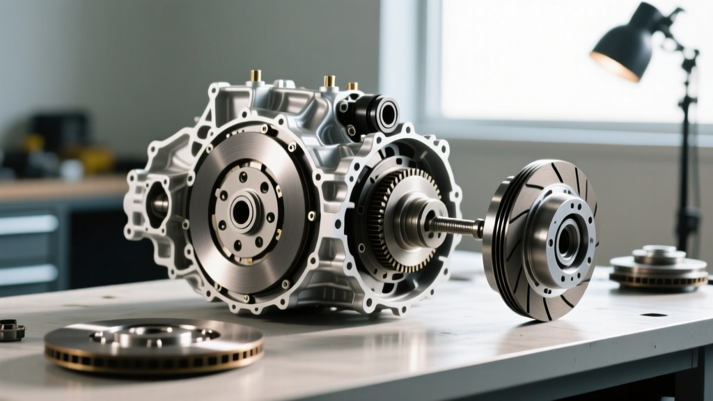
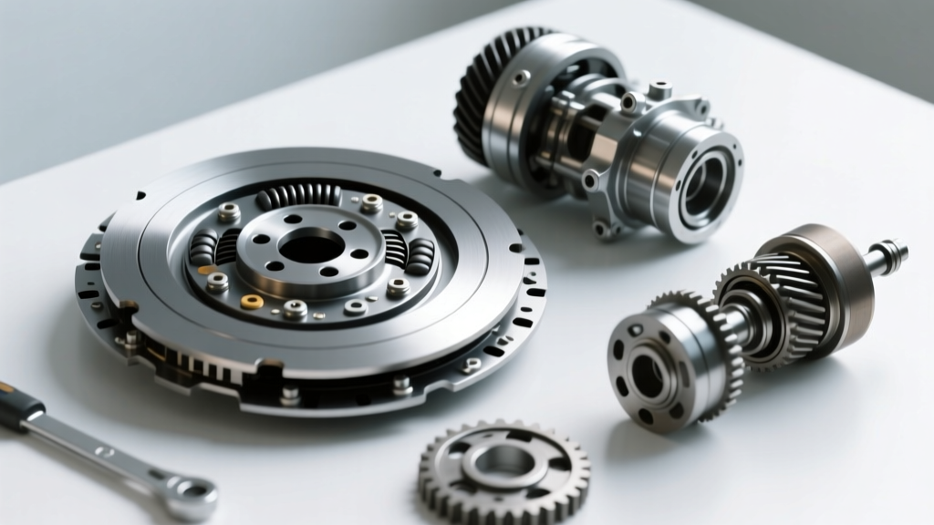
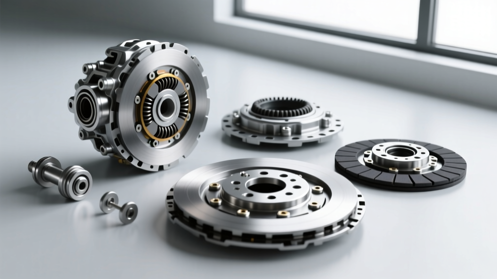
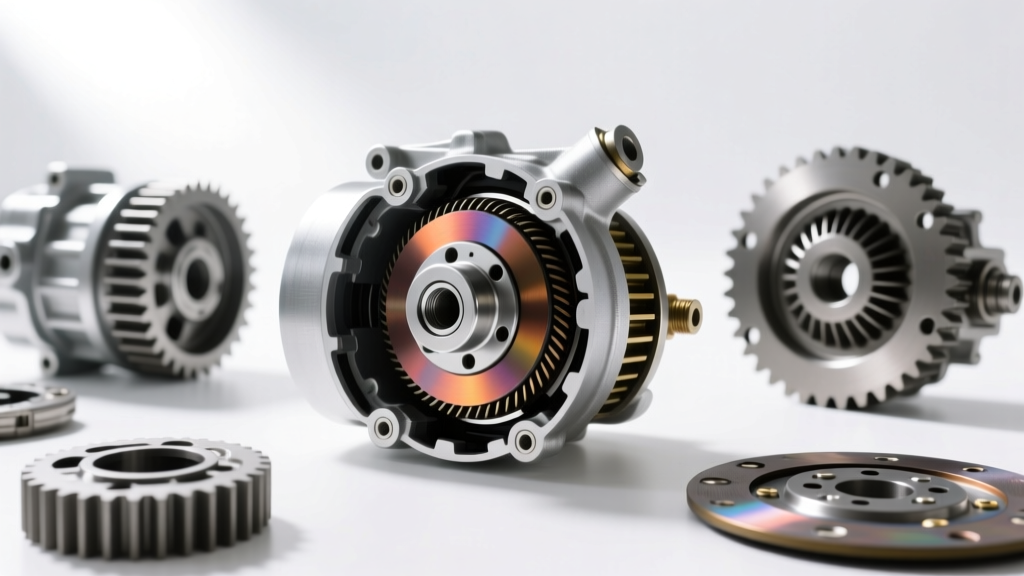
Before making a repair decision, you must isolate which of the three clutch sub-components has failed. The clutch assembly consists of:
- The Hub/Drive Plate: The friction surface that locks onto the pulley when magnetized, transferring engine torque to the compressor's internal swash plate or scroll mechanism.
- The Pulley and Bearing: Driven continuously by the serpentine belt. It houses the electromagnetic coil and spins freely on a sealed angular contact bearing when the AC is off.
- The Electromagnetic Coil: A copper winding that generates the magnetic flux required to pull the hub against the pulley face, overcoming the air gap.
Failures typically manifest in three ways: electrical (open coil or blown thermal fuse), mechanical (seized pulley bearing or worn friction surfaces), or contamination-related (refrigerant oil on the friction plate). Identifying the exact failure mode is the crux of the repair vs. replace decision.
Step 2: The Repair vs. Replace Decision Matrix
Use the following diagnostic matrix to determine whether a standalone automotive air conditioning compressor clutch replacement is viable, or if the entire compressor assembly must be replaced.
| Symptom / Finding | Root Cause | Verdict: Clutch Kit vs. Full Compressor |
|---|---|---|
| Clutch won't engage; 12V present at plug; infinite resistance at coil pins. | Open circuit in electromagnetic coil or blown thermal limiter. | Replace Clutch Coil/Kit. Compressor internals are likely fine. |
| High-pitch squealing or grinding noise from pulley; clutch disengaged. | Seized or failing pulley bearing. | Replace Clutch Pulley/Bearing. Compressor shaft seal is intact. |
| Clutch engages but slips under high RPM; visible oil mist on friction plate. | Compressor front shaft seal failure leaking PAG/POE oil onto clutch. | Replace Full Compressor. A new clutch will slip and burn up immediately. |
| Clutch engages, but compressor makes internal knocking noises; no cooling. | Internal swash plate or piston failure; broken connecting rods. | Replace Full Compressor. Clutch is fine, but the driven load is destroyed. |
| Clutch drags when AC is turned off; hub is discolored (blued from heat). | Air gap too narrow; thermal damage to coil insulation. | Replace Clutch Kit. Requires precise reshimming during installation. |
Step 3: The Shaft Seal Trap (Critical Diagnostic Step)
The most common mistake DIYers and novice technicians make is performing an automotive air conditioning compressor clutch replacement on a unit that actually has a leaking front shaft seal. Modern compressors, such as the Denso 10S17C or Sanden SD7V16, utilize high-viscosity PAG or POE oils. When the shaft seal weeps, centrifugal force throws this oil directly onto the clutch friction surfaces.
Oil drastically reduces the coefficient of friction. The clutch will slip, generating immense heat, which eventually burns out the electromagnetic coil's thermal fuse. If you replace the clutch without addressing the leaking seal, the new clutch will fail within weeks. Rule of thumb: If you see a thick, dark, oily residue on the pulley face or hub, abandon the clutch replacement and budget for a full compressor swap, system flush, and receiver-drier replacement.
Step 4: Measuring and Adjusting the Air Gap
If your diagnostic points to a bad coil or worn friction surfaces, and the shaft seal is dry, you are cleared for a clutch replacement. However, the most critical step in the installation is setting the air gap. This is the physical distance between the pulley face and the hub plate.
- Specification: Most OEM manufacturers (including GM, Ford, and Toyota) specify an air gap between 0.4mm and 0.6mm (0.015' to 0.025').
- Too Wide (>0.8mm): The magnetic flux cannot overcome the gap, especially when the coil gets hot and resistance increases. The clutch will slip and burn.
- Too Narrow (<0.3mm): Thermal expansion of the metals will cause the hub to drag against the pulley when the AC is turned off, destroying the pulley bearing and generating parasitic drag on the engine.
How to adjust: The air gap is adjusted using precision shims located on the compressor shaft behind the hub. Clutch kits usually include an assortment of shims (e.g., 0.1mm, 0.2mm, 0.5mm). Use a non-magnetic brass feeler gauge to measure the gap at three equidistant points around the circumference to ensure the hub is not bent.
Step 5: Executing the Replacement Procedure
Performing the physical swap requires specific tools to prevent damage to the delicate threads on the compressor's front shaft.
Tools Required
- AC Clutch Holding Tool (e.g., Lisle 45750 or OEM-specific spanner)
- Clutch Hub Puller (3-jaw or specific threaded puller)
- Internal/External Snap Ring Pliers
- Non-magnetic Feeler Gauge Set
- Torque Wrench (inch-pounds capable)
Step-by-Step Execution
- Remove the Center Bolt: Use the clutch holding tool to lock the hub in place. Remove the center bolt. Warning: Do not use an impact wrench, as the shock loading can shatter the internal ceramic swash plate bearings.
- Pull the Hub: Thread the puller tool into the hub and extract it from the shaft. Note the number and thickness of the shims behind the hub. Keep them organized.
- Remove the Pulley: Use snap ring pliers to remove the large retaining snap ring. Slide the pulley and bearing assembly off the compressor snout. If it is seized, apply penetrating fluid and use a bearing puller; never hammer the snout.
- Replace the Coil: Remove the coil retaining snap ring. Slide the old coil off. Clean the snout with brake cleaner. Slide the new coil on, ensuring the anti-rotation tab seats perfectly in the compressor housing notch. Reinstall the snap ring.
- Reassemble and Shim: Slide the pulley back on and secure with the snap ring. Install your calculated shims onto the shaft, followed by the hub. Hand-thread the new center bolt.
- Torque and Verify: Torque the center bolt to OEM specifications. For most Denso and Sanden units, this is 11 to 15 Nm (8 to 11 lb-ft). Over-torquing will strip the aluminum shaft threads; under-torquing will allow the hub to walk and destroy the keyway. Re-check the air gap with your feeler gauge.
Step 6: Electrical Validation and Coil Resistance Testing
Before reassembling the engine bay, validate the new coil. According to the Mobile Air Climate Systems Association (MACS), a standard 12V AC clutch coil should exhibit a resistance between 3.0 and 5.0 ohms at 20°C (68°F). If your multimeter reads outside this range, the replacement part is defective or incompatible with your vehicle's specific compressor model.
Furthermore, test the voltage at the clutch connector with the engine running and the AC commanded ON. You must see full system voltage (13.5V - 14.2V). A voltage drop caused by a corroded relay or poor chassis ground will result in insufficient magnetic pull, leading to premature clutch failure. As noted in Sanden International's technical service bulletins, variable displacement compressors rely heavily on consistent clutch engagement to manage internal control valve pressures; voltage starvation will cause erratic cooling performance.
Cost Analysis: Clutch Kit vs. Full Compressor Assembly (2026 Estimates)
Understanding the financial implications helps solidify the repair decision. Below is a breakdown of average parts and labor costs for a standard passenger vehicle (e.g., Honda Accord, Ford F-150, Toyota Camry).
- Clutch Kit (Coil, Pulley, Hub, Shims): $65 - $180
- Full OEM Compressor Assembly: $350 - $850+
- Labor (Clutch Replacement Only): $150 - $250 (Often can be done without evacuating the refrigerant system if space permits, saving $100+ in AC recovery/recharge fees).
- Labor (Full Compressor Replacement): $300 - $600 (Includes refrigerant recovery, vacuum testing, and R-1234yf or R-134a recharge).
If the compressor shaft seal is dry and the internal mechanics are quiet, the automotive air conditioning compressor clutch replacement is a highly cost-effective repair that saves hundreds of dollars in refrigerant handling and parts costs. However, if internal noise or oil leaks are present, the clutch kit is merely a band-aid on a terminal mechanical failure.
Conclusion
The decision to perform an automotive air conditioning compressor clutch replacement rather than swapping the entire unit hinges entirely on rigorous diagnostics. By inspecting for shaft seal leaks, measuring coil resistance, and meticulously setting the air gap to OEM tolerances, you can restore your vehicle's climate control system to factory efficiency. Always prioritize precision measurement over brute force, and remember that in high-pressure R-1234yf systems, the margin for error on clutch air gaps is smaller than ever.