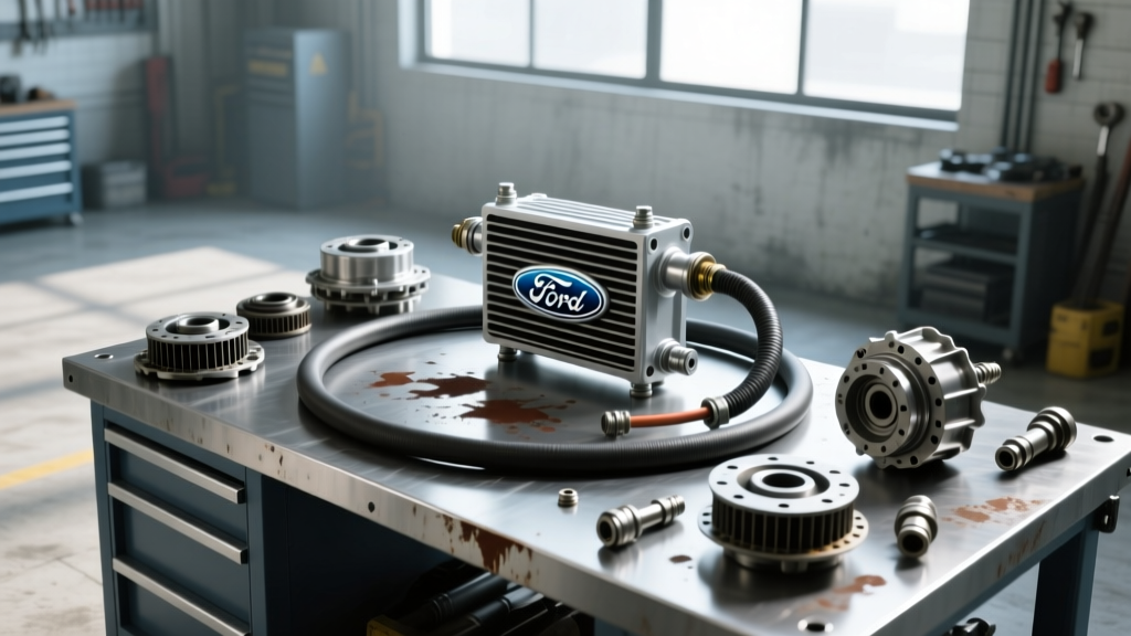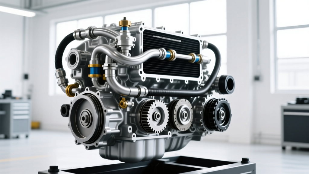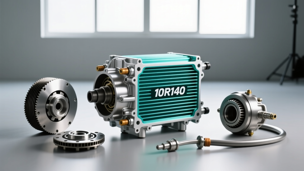
The 10R140 Thermal Management Challenge
The Ford 10R140 TorqShift transmission is an engineering marvel, designed to handle the immense torque of the 3.5L EcoBoost V6, the 7.3L Godzilla V8, and the 6.7L Power Stroke diesel in heavy-duty applications. However, managing the thermal load generated by ten forward gears, a high-stall torque converter, and aggressive towing profiles requires a robust and unobstructed cooling system. As we navigate the 2026 maintenance landscape, preventive care for the 10R140 transmission cooler is no longer optional—it is a critical requirement for longevity.
Unlike older 6-speed automatics, the 10R140 operates with tighter internal clearances and relies heavily on Ultra Low Viscosity (ULV) fluid. When clutch material, metallic wear particles, or degraded fluid varnish accumulate in the transmission cooler and associated lines, flow restriction occurs. This leads to delayed thermal bypass valve engagement, localized overheating, and ultimately, premature failure of the mechatronic solenoids.
Understanding the 10R140 Cooler Circuit Architecture
To properly flush the system, technicians and DIYers must understand how the 10R140 routes fluid. The transmission utilizes an internal Thermal Bypass Valve (TBV). During cold starts, the TBV restricts fluid flow to the external cooler, forcing the fluid to recirculate internally to reach optimal operating temperature quickly (typically between 185°F and 195°F).
The Danger of Debris Traps
If a flush is neglected, microscopic clutch friction material bypasses the internal filter and lodges in the TBV or the narrow micro-channels of the auxiliary stacked-plate cooler. When the TBV attempts to open at 185°F, the debris prevents full stroke travel. The result? The transmission continues to recirculate hot fluid internally while the cooler remains starved, triggering the 'Transmission Over Temp' limp-mode warning on the dashboard.
Critical Specifications: Fluids, Torque, and Capacities
Using the incorrect fluid in a 10R140 will destroy the clutches within a few hundred miles due to friction modifier incompatibility. Always adhere to the following OEM specifications when performing a cooler flush or full system exchange.
| Parameter | Specification / Value |
|---|---|
| Fluid Type | MERCON ULV (Ultra Low Viscosity) |
| Motorcraft Part Number | XT-12-QULV |
| Total System Capacity | 13.1 Quarts (12.4 Liters) |
| Cooler & Lines Capacity | ~1.8 Quarts |
| Leveling Plug Torque | 22 lb-ft (30 Nm) |
| Flare Nut Torque (if equipped) | 18 lb-ft (24 Nm) |
| Thermal Bypass Opening Temp | ~185°F (85°C) |
Source: Motorcraft Fluid Specifications
Required Tools for the Cooler Flush
Before elevating the vehicle, gather the following specialized tools. Standard wrench sets are insufficient for modern Ford quick-connect fittings.
- Line Disconnect Tool: Lisle 44800 or OTC 4796 (specifically for 1/2-inch and 5/8-inch Ford transmission cooler quick-connects).
- Flush Tank / Exchange Machine: A pneumatic or manual reverse-flush tank capable of delivering 40-60 PSI of air/fluid pressure.
- Drain Pans: Minimum 5-gallon capacity to catch residual line fluid.
- Infrared Thermometer: For post-flush thermal cycling verification.
Step-by-Step 10R140 Cooler and Line Flush Procedure
This procedure focuses specifically on isolated cooler and line flushing, which is recommended every 30,000 miles for severe-duty vehicles, or as a prerequisite when replacing a failed 10R140 transmission to prevent cross-contamination.
Phase 1: Preparation and Line Disconnection
- Elevate the vehicle on a two-post lift or jack stands. The vehicle must be perfectly level to ensure accurate fluid leveling later.
- Locate the transmission cooler lines at the rear of the 10R140 transmission case. Identify the 'Out' (pressure to cooler) and 'In' (return from cooler) lines.
- Slide the Lisle disconnect tool over the quick-connect fitting until you hear the internal retaining tabs disengage. Pull the line straight out. Note: Have a drain pan ready, as approximately 0.5 quarts of fluid will drain from the transmission side.
- Cap the transmission output ports immediately with clean rubber caps to prevent environmental contamination.
Phase 2: Reverse-Flushing the Cooler Circuit
Never flush in the direction of normal flow. Normal flow pushes debris deeper into the stacked-plate fins. Reverse flushing dislodges trapped material.
- Connect your flush tank to the Return Line (the line that normally feeds fluid back into the transmission).
- Route the Pressure Line (the line coming from the transmission) into a 5-gallon catch basin.
- Charge the flush tank with a dedicated transmission cooler flush solvent or fresh MERCON ULV fluid.
- Apply 40-50 PSI of pressure in short, pulsing bursts (3 seconds on, 2 seconds off). This pulsing creates a hydraulic shockwave that breaks up varnish and clutch material trapped in the thermal bypass valve and cooler fins.
- Continue until the fluid exiting the pressure line into the catch basin runs completely clear and free of metallic glitter.
Phase 3: Reconnection and Thermal Cycling
- Lubricate the O-rings on the transmission cooler lines with a few drops of fresh MERCON ULV fluid.
- Push the quick-connect fittings back into the transmission ports until you feel and hear a distinct 'click'. Pull back firmly to verify engagement.
- Top off the transmission fluid via the leveling plug on the rear of the pan to compensate for the 1.8 quarts lost during the cooler flush.
- Start the engine, apply the parking brake, and cycle through all gears (P-R-N-D) pausing for 3 seconds in each.
Diagnosing Post-Flush Flow Restrictions
After the flush, you must verify that the Thermal Bypass Valve is operating correctly. Using an infrared thermometer or an OBD2 bi-directional scan tool monitoring the Transmission Fluid Temperature (TFT) PID, observe the cooler line temperatures.
Expert Diagnostic Tip: During a cold start, the cooler 'In' line should remain relatively cool while the transmission fluid heats up. Once the internal TFT reaches 185°F, the 'In' line temperature should spike rapidly, indicating the TBV has opened and fluid is flowing to the cooler. If the line temperature does not spike, the TBV is mechanically stuck, requiring pan removal and valve body inspection.
For deeper insights into 10R140 valve body diagnostics and thermal management, refer to the Sonnax Technical Resources database, which provides extensive teardown analysis of Ford's 10-speed architecture.
2026 Cost Breakdown: Dealership vs. DIY
Maintenance costs have shifted in recent years due to the rising price of synthetic ULV fluids and specialized labor rates. Below is a comparative look at what you can expect to pay for 10R140 cooling system maintenance in 2026.
| Service Type | Estimated Cost | Pros & Cons |
|---|---|---|
| Dealership Full Machine Exchange | $350 - $480 | Replaces all 13.1 qts; expensive; relies on dealer equipment maintenance. |
| Independent Shop Cooler Flush | $150 - $220 | Cost-effective; targets the cooler; requires shop to have Ford-specific adapters. |
| DIY Cooler Flush & Top-Off | $65 - $95 | Highly controlled; requires purchase of disconnect tools and 3-4 qts of MERCON ULV. |
Expert Maintenance Intervals
Ford's official maintenance guides often list the 10R140 transmission fluid as a 'lifetime' fill under normal driving conditions. However, as any heavy-duty towing specialist will confirm, 'lifetime' merely means the lifespan of the warranty.
For vehicles subjected to severe duty (towing over 5,000 lbs, frequent off-roading, or commercial fleet use), we recommend a dedicated 10R140 transmission cooler and line flush every 30,000 miles, paired with a full pan-drop and filter replacement every 60,000 miles. The internal filter is a coarse mesh designed to protect the pump, not to capture microscopic clutch dust. That dust ends up in your cooler. By isolating and reverse-flushing the cooler circuit, you protect the delicate mechatronic unit and ensure the 10R140 continues to deliver seamless, heat-managed shifts for hundreds of thousands of miles.